162 Rockwell Automation Publication 750-UM006C-EN-P - March 2022
Chapter 5 Drive Maintenance
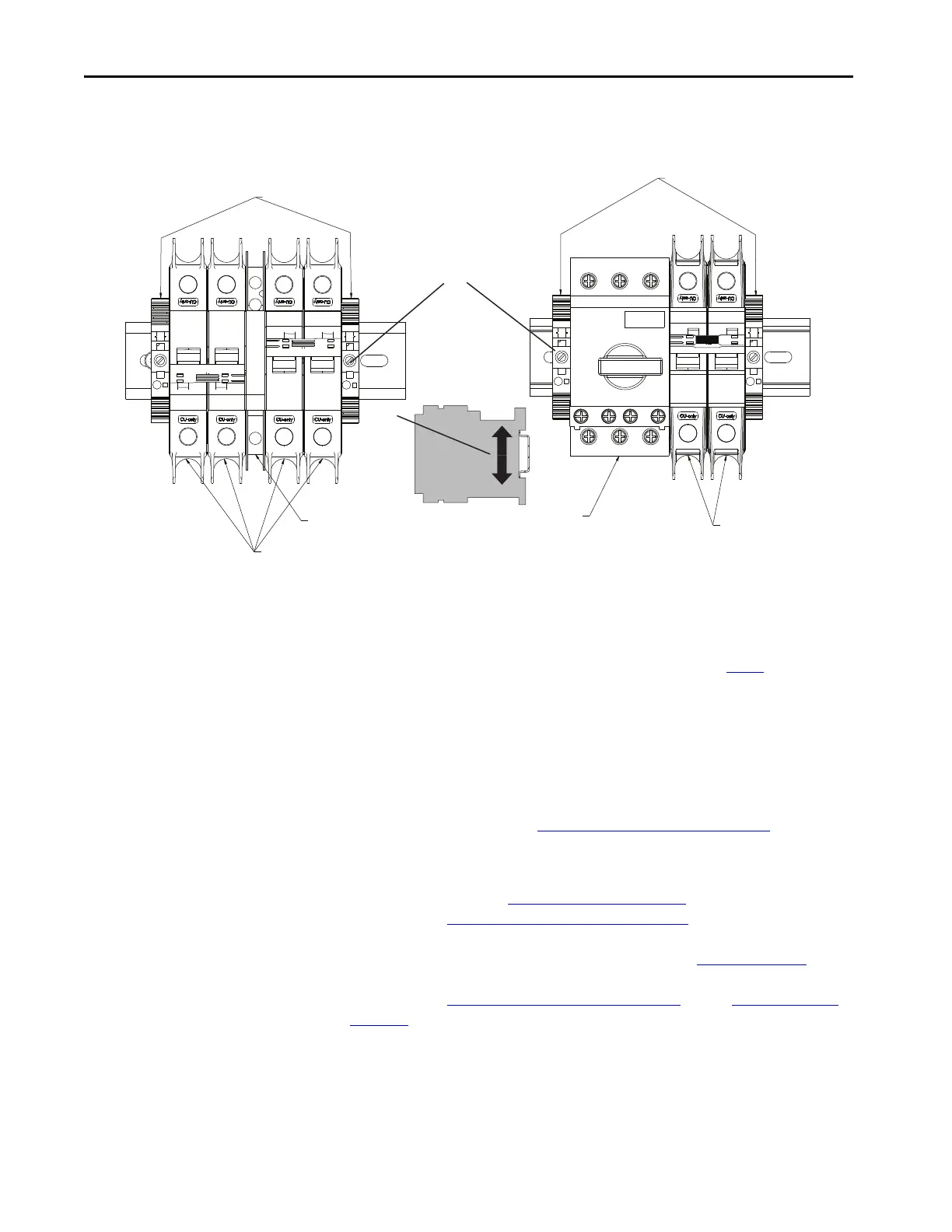
5. Use a flathead screwdriver to dislodge the circuit breaker from the DIN
rail.
6. Unpack and inspect the new circuit breaker.
7. Attach the circuit breaker to the DIN Rail.
8. Use a flathead screwdriver to attach the wires from step 3
to the
terminals.
Torque screws to 12 lb•in.
9. Set the end anchors in place and use a flathead screwdriver to tighten
their screws.
Torque screws to 4.4 lb•in.
10. Follow instructions to Attach the Front Cover
on page 169.
Replace the Drive HIM
(1HIM320)
Follow the procedure to Remove Power on page 146 and follow the
instructions to Remove the Front Cover
on page 148. For information on how
to replace the HIM, see PowerFlex 20-HIM-A6 and 20-HIM-C6S HIM
(Human Interface Module) User Manual, publication 20HIM-UM001
to
install the 20-HIM-CS6 HIM. After the HIM is replaced, follow the
instructions to Attach the Front Cover
on page 169. and to Apply Power on
page 170.
End Anchors
End Anchors
4 (x2)
Auxiliary Contact
Cat. No. 1489-AMRA3
Auxiliary Breakers
Cat. No. 1489-M2D040
Auxiliary Circuit Breaker
Cat. No. 140M-C2E-B25/
140MT-C3E-B25 and Auxiliary Contact
140M-C-AFA10/140MT-C-AFA10
Auxiliary Circuit Breaker
Cat. No. 1489-M2D040
Side View

 Loading...


