x530 Series Installation Guide for Stand-alone Switches
123
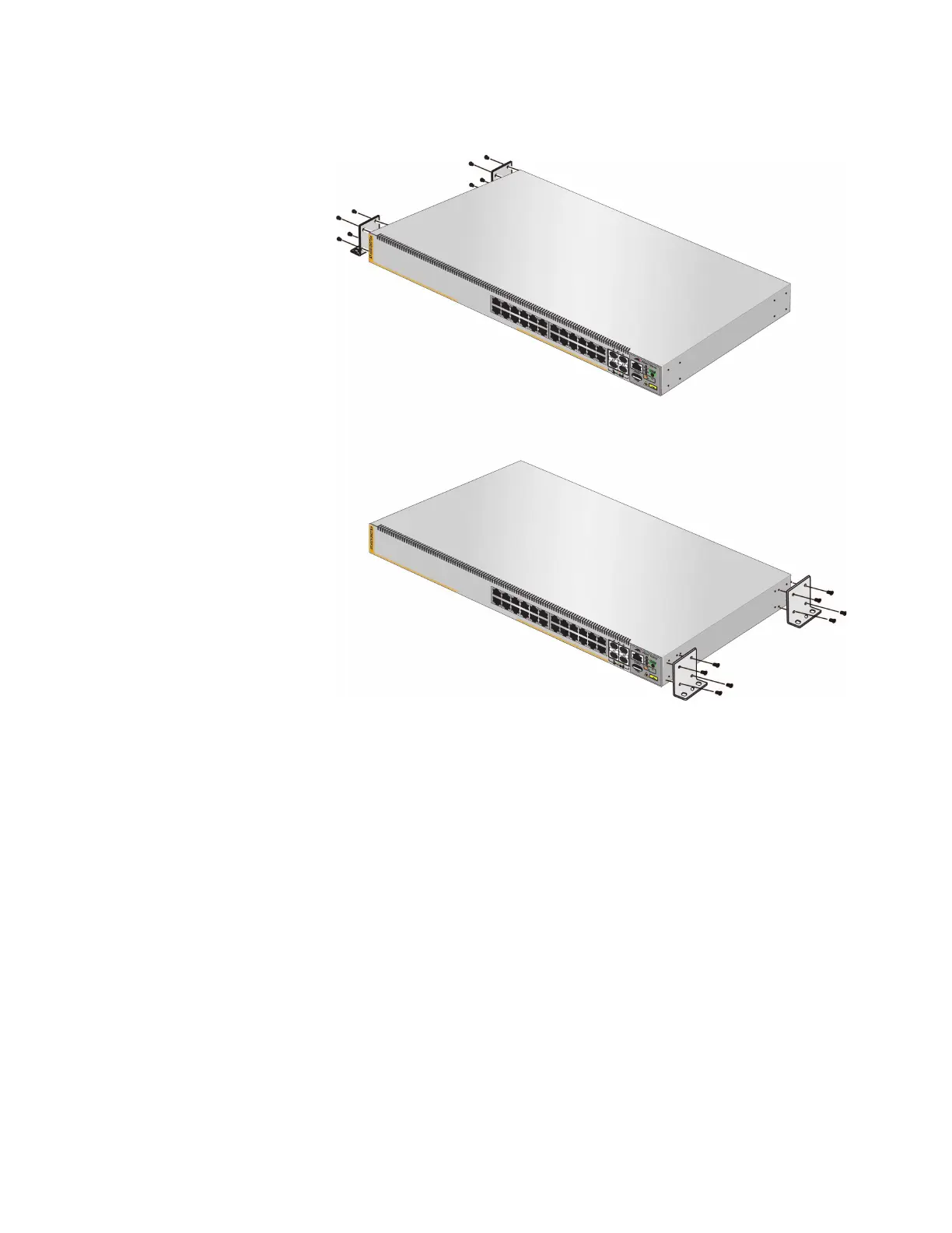
Figure 46. Installing Two Brackets on the x530-28GTXm or x530-28GSX
Switch
Brackets positions
the front panel on the left.
to install the switch with
Brackets positions
the front panel on the right.
to install the switch with

 Loading...


