EasyManuals Logo

Allied Telesis x530 Series User Manual

Allied Telesis x530 Series
200 pages
To Next Page IconTo Next Page
To Previous Page IconTo Previous Page
Page #106 background imageLoading...
Page #106 background image
Chapter 4: Installing the Switch on a Table
106
Figure 34. Holes for Bumper Feet
To install the switch on a table, perform the following procedure:
1. Place the switch upside down on a table.
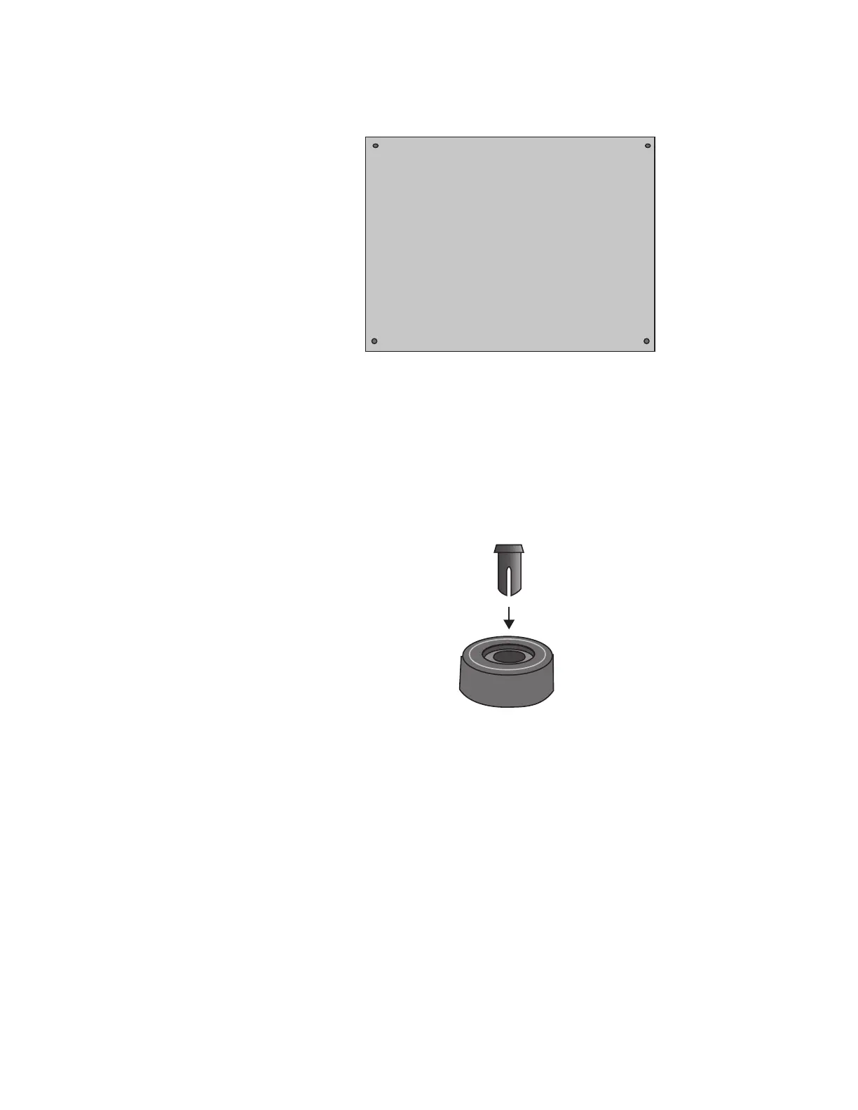
2. Insert a rivet housing into a bumper foot. Refer to Figure 35.
Figure 35. Inserting the Rivet Housing into the Bumper Foot
Rear of Chassis
Front of Chassis

Table of Contents

Other manuals for Allied Telesis x530 Series

Questions and Answers:

Question and Answer IconNeed help?

Do you have a question about the Allied Telesis x530 Series and is the answer not in the manual?

Allied Telesis x530 Series Specifications

General IconGeneral
BrandAllied Telesis
Modelx530 Series
CategorySwitch
LanguageEnglish

Related product manuals