x530 Series Installation Guide for Virtual Chassis Stacking
53
The states of the LED when the switch is not operating in the low power
mode are shown in Figure 18.
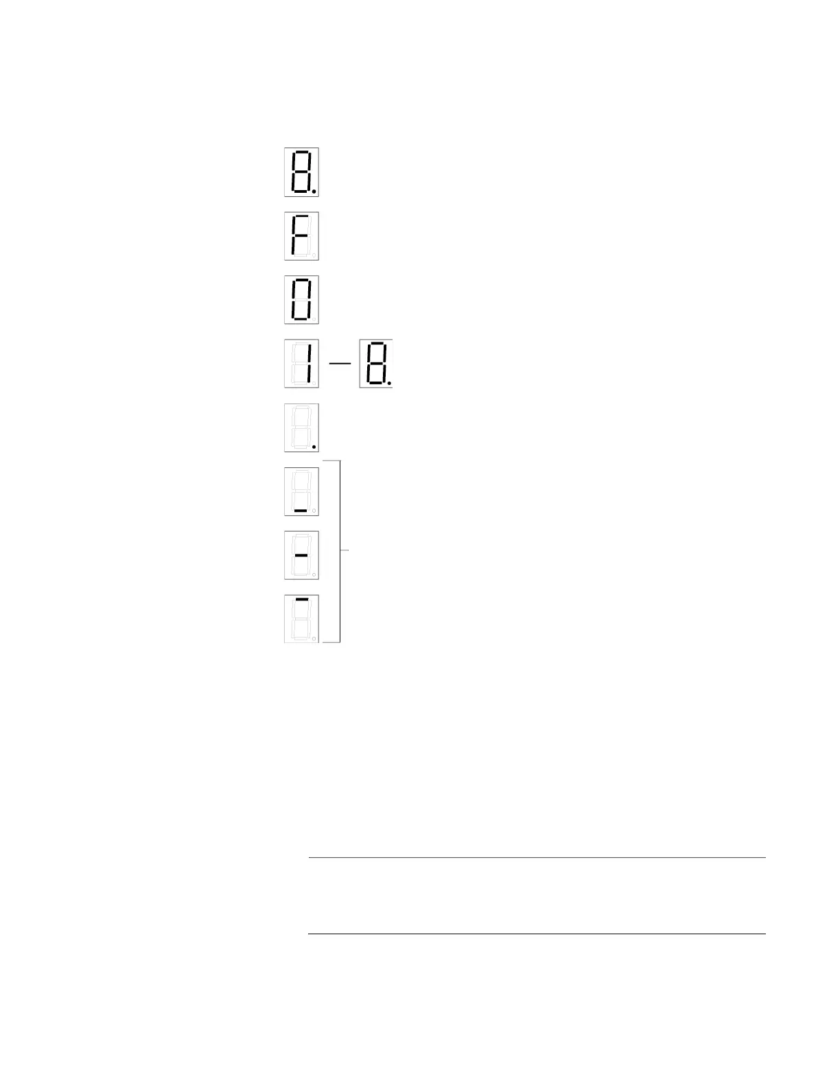
Figure 18. Switch ID LED Description
The switch displays the letter “F” for fault on the ID LED if it detects one of
the following problems:
A cooling fan has failed.
The input voltage on one or both of the power supplies is outside
the normal operating range.
The internal temperature of the switch has exceeded the normal
operating range and the switch may shut down.
Note
You can use the Simple Network Management Protocol (SNMP) or
the SHOW SYSTEM ENVIRONMENT command in the command
line interface to identify the source of the problem.
The switch is booting up.
The switch has encountered a fault condition.
The switch is operating as a standalone unit.
The switch has an ID number of 1 to 8 as part of a
The dot in the lower right corner flashes when the switch
accesses USB memory.
VCStack.
When the eco-friendly mode is enabled, the front panel LEDs
are in OFF mode. The horizontal segments will be lit up to
show power status and mode of stacking:
Upper segment: Master
Middle segment: Standalone
Lower segment: Member
No segment illuminated: No Power

 Loading...


