x530 Series Installation Guide for Virtual Chassis Stacking
45
Note
See “SFP/SFP+ Transceiver Ports” on page 23 for descriptions of
the LEDs for the SFP/SDP+ ports.
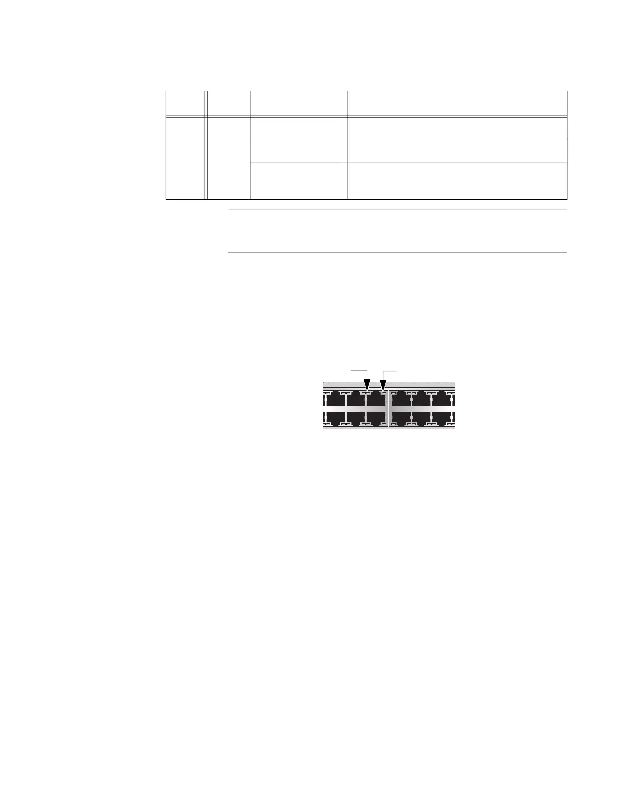
x530-28GPXm and x530-52GPXm
The x530-28GPXm and x530-52GPXm LEDs indicate Link/Activity (L/A)
and PoE (PD ON/PD ERR/MAX CURRENT) information. These LEDs are
shown in Figure 14.
Figure 14. x530-28GPXm and x530-52GPXm Copper Ports LEDs
D/C 1 - 48
Solid Green The port is operating in full-duplex mode.
Solid Amber The port is operating in half-duplex mode.
Flashing Amber The port is operating in half-duplex mode
with collisions.
Table 13. x530-52GTXm Copper Ports 1 - 48 LED Functions (Continued)
LED Ports State Description
7 9 11 13 15 17
16 1814
81012
L/A LED PoE LED

 Loading...


