Chapter 1: Overview
52
The LEDs display link status and activity. The possible LED states are
described in Table 17.
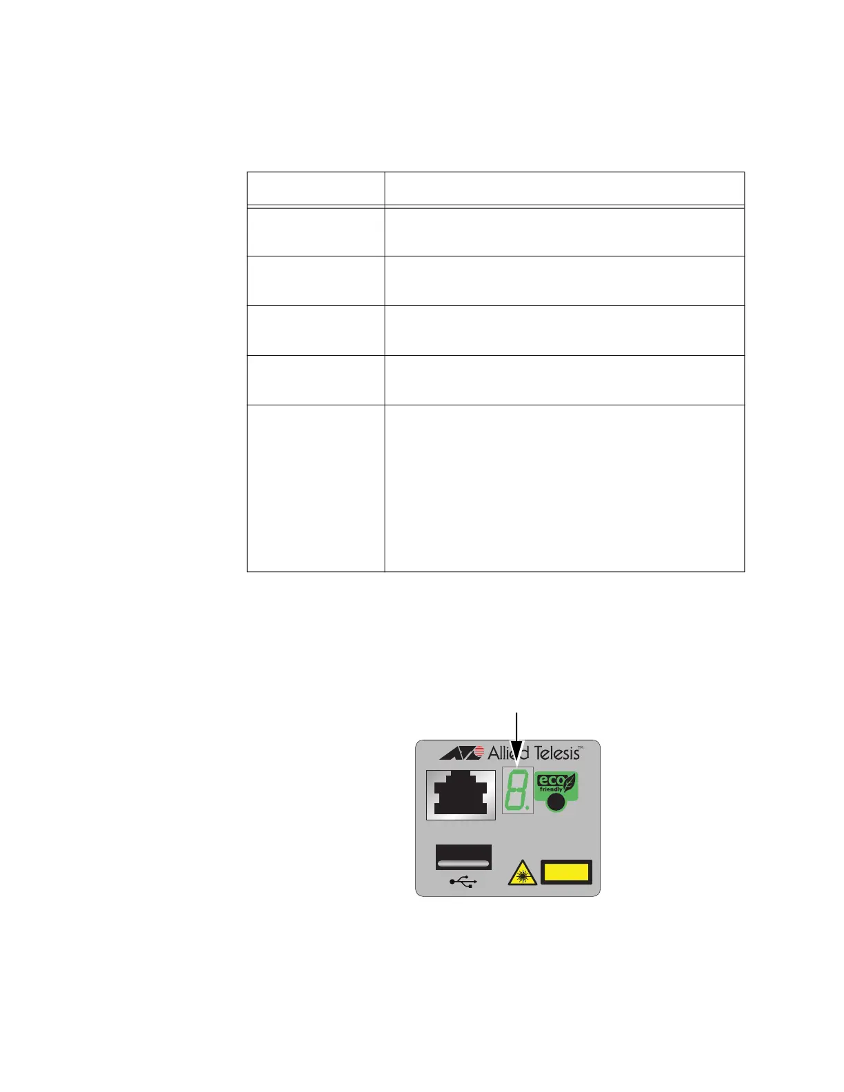
Switch ID LED The switch ID LED, shown in Figure 17, displays the ID number of the
switch. A standalone switch has the ID number 0. Switches in a VCStack
have the numbers 1 to 8.
Figure 17. Switch ID LED
Table 17. Link and Activity Status LEDs for the 1Gbps and 10Gbps Ports
State Description
Solid Green The transceiver has established a 10Gbps link to a
network device.
Flashing Green The transceiver is transmitting or receiving data in
10Gbps.
Solid Amber The transceiver has established a 1Gbps link to a
network device.
Flashing Amber The transceiver is transmitting or receiving data in
1Gbps.
Off Possible causes of this state are:
- The port is empty.
- The transceiver has not established a link to a
network device.
- A non-supported module is installed.
- The LEDs are turned off. To turn on the LEDs, use
the eco-friendly button.
CLASS
1
LASER PRODUCT
CONSOLE
4567
Switch
ID LED

 Loading...


