x530 Series Installation Guide for Virtual Chassis Stacking
99
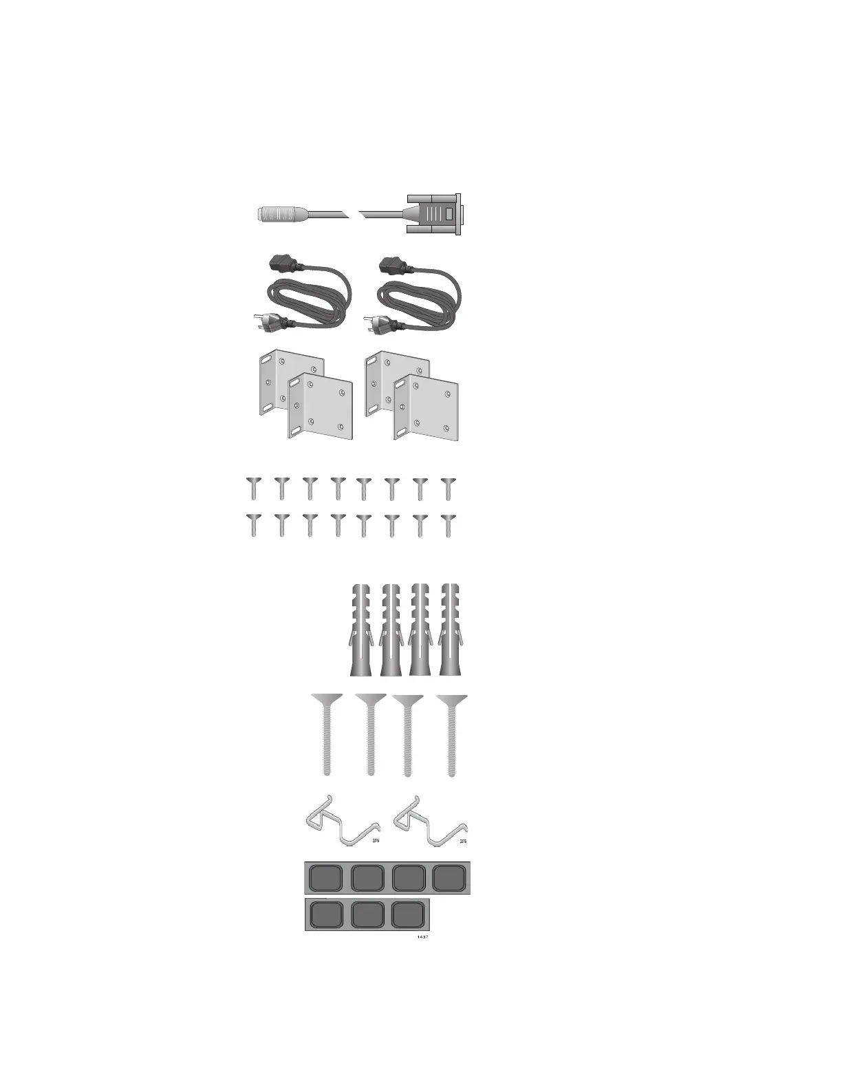
Figure 31 lists the items that are included in the accessory kit for the x530-
28GPXm, x530-28GTXm, x530-28GSX, x530-52GPXm, and x530-
52GTXm. Contact your Allied Telesis sales representative for assistance if
any item is missing or damaged.
Figure 31. Accessory Kit Items
Two or four wall/equipment rack
brackets depending on the model.
One 2m (6.6 ft) local management
cable with RJ-45 (8P8C) and DB-9
(D-sub 9-pin) connectors.
Eight or sixteen screws for attaching
the wall/equipment rack brackets
depending on the model.
Length: 6.0mm (0.2 in.)
Diameter: 4.0mm (0.2 in.)
Two regional AC power cords.
Two or four anchors for concrete
walls depending on the model.
Length: 29.6mm (1.2 in.)
Diameter: 6.0mm (0.2 in.)
Two or four screws for wood or concrete
walls depending on the model.
Length: 32mm (1.3 in.)
Diameter: 4mm (0.2 in.)
3375
1570
Two power cord retaining clips
1947
1947
2047
Seven rubber feet

 Loading...


