x530 Series Installation Guide for Virtual Chassis Stacking
107
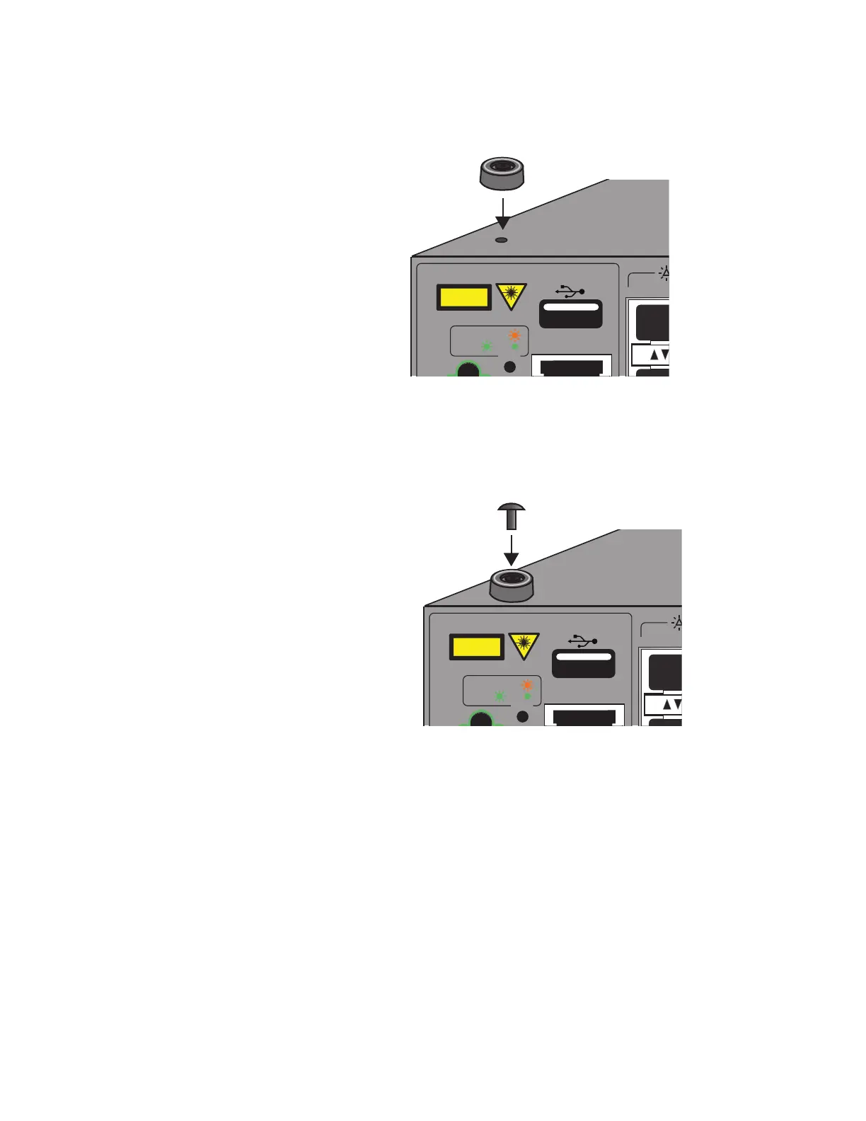
3. Place the bumper foot with rivet housing onto one of the holes in the
base of the switch. Refer to Figure 36.
Figure 36. Placing the Bumper Foot on a Base Corner Hole
4. Insert the rivet to secure the bumper foot to the base. Refer to Figure
37 on page 107.
Figure 37. Inserting the Rivet into the Bumper Foot
5. Repeat steps 2 to 4 to install the remaining bumper feet.
6. Turn the switch over and place it on a flat, secure desk or table, leaving
ample space around it for ventilation.
USB
ON ACT
ERR
CLASS 1
LASER PRODUCT
CONSOLE
USB
ON ACT
ERR
CLASS 1
LASER PRODUCT
CONSOLE

 Loading...


