System design
24 Edition 01/2016 multi EA 4000
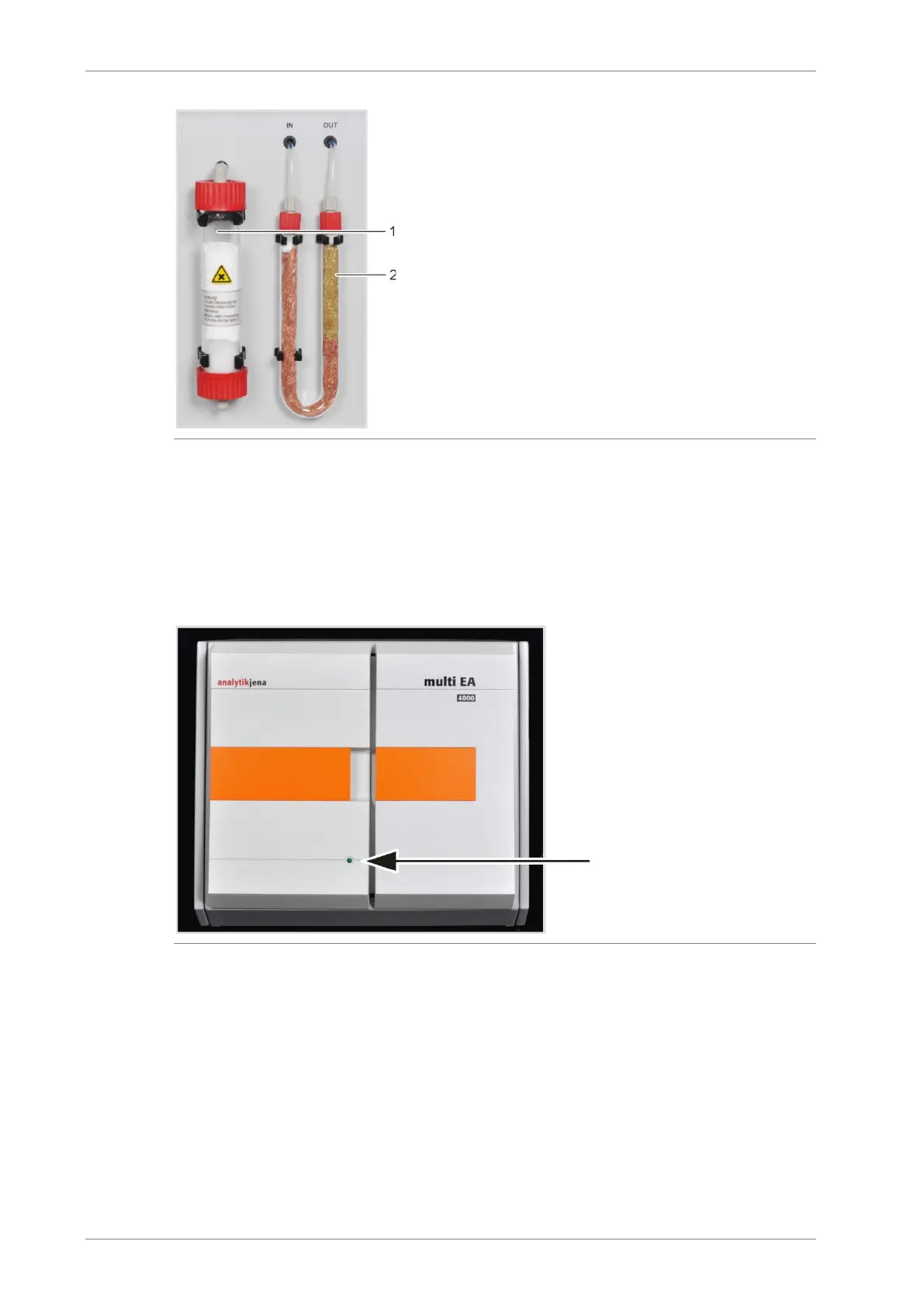
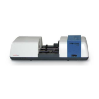
1 drying tube with magnesium perchlorate
2
halide trap
Fig. 4 Drying tube and halide trap
4.2.4 Indicator and control elements, connections
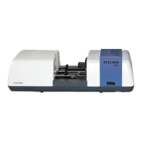
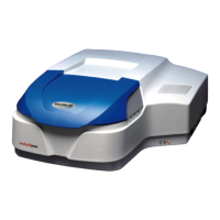
The green LED at the left door of the analyzer illuminates after the analyzer has been
switched on.
Fig. 5 Status indicators at the basic device multi EA 4000
Behind the front doors there are the mains switch and the flow meters for the manual control
of the gas flows.