System design
32 Edition 01/2016 multi EA 4000
4.4.4 Connections
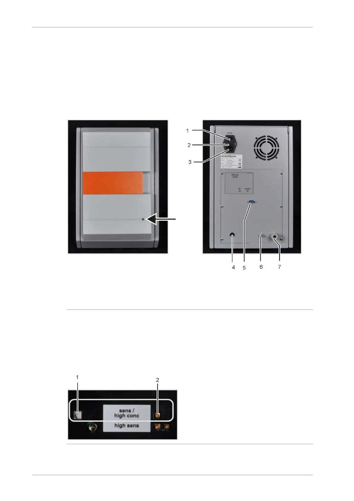
The green LED located at the front of the Cl module illuminates once the module has been
switched on.
Dependent on the equipment of the multi EA 4000 with or without C/S module, the connec-
tion for attachment to the C/S module or the basic device and the sampler are found on the
rear. The rear also features the outlet for the bypass in splitting mode.
The hoses for the supply of measuring gas and the bypass are passed through the duct in
the basic device through the opening in the right-hand device panel to the chlorine module.
1 mains plug connection
2
fuse holder
connection not allocated for the multi EA 4000
5 connection "Cl-Coul" – connection to the C/S mod-
ule
gas connection "Cl" – connection to the C/S module
gas outlet "waste"
Fig. 16 Connections of the Cl module in combination with a C/S module
Note:
If no C/S module has been installed, the Cl module has additional interfaces on the rear for
the communication with the EA 4000 and the sampler. The interface allocation has been
described in section "Installing the multi EA 4000 Cl" p. 125.
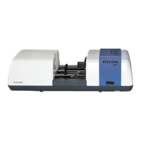
The electrical connections for the measuring cell and the combination electrode are located
on the inside of the device backplate.
1 connection for combination electrode
2
connection of the measuring cell with silver anode
Fig. 17 Connections for the coulometric cell at the inside panel of the Cl module