System design
multi EA 4000 Version 01.16 27
constant gas flow by computer-controlled normalization of the signal and only integrated
afterwards.
To detect the measuring gas flow a flow sensor is arranged very close to the NDIR detector
flow.
Gas flow control
A flow meter monitors the necessary intake flow; the values are captured in the software.
Deviations from the permissible target value are indicated, and the intake flow can be cor-
rected at the "pump" valve of the flow meter of the basic device multi EA 4000 (3 in Fig. 6).
During a measurement the values are used for the integrated correction using the VITA
method.
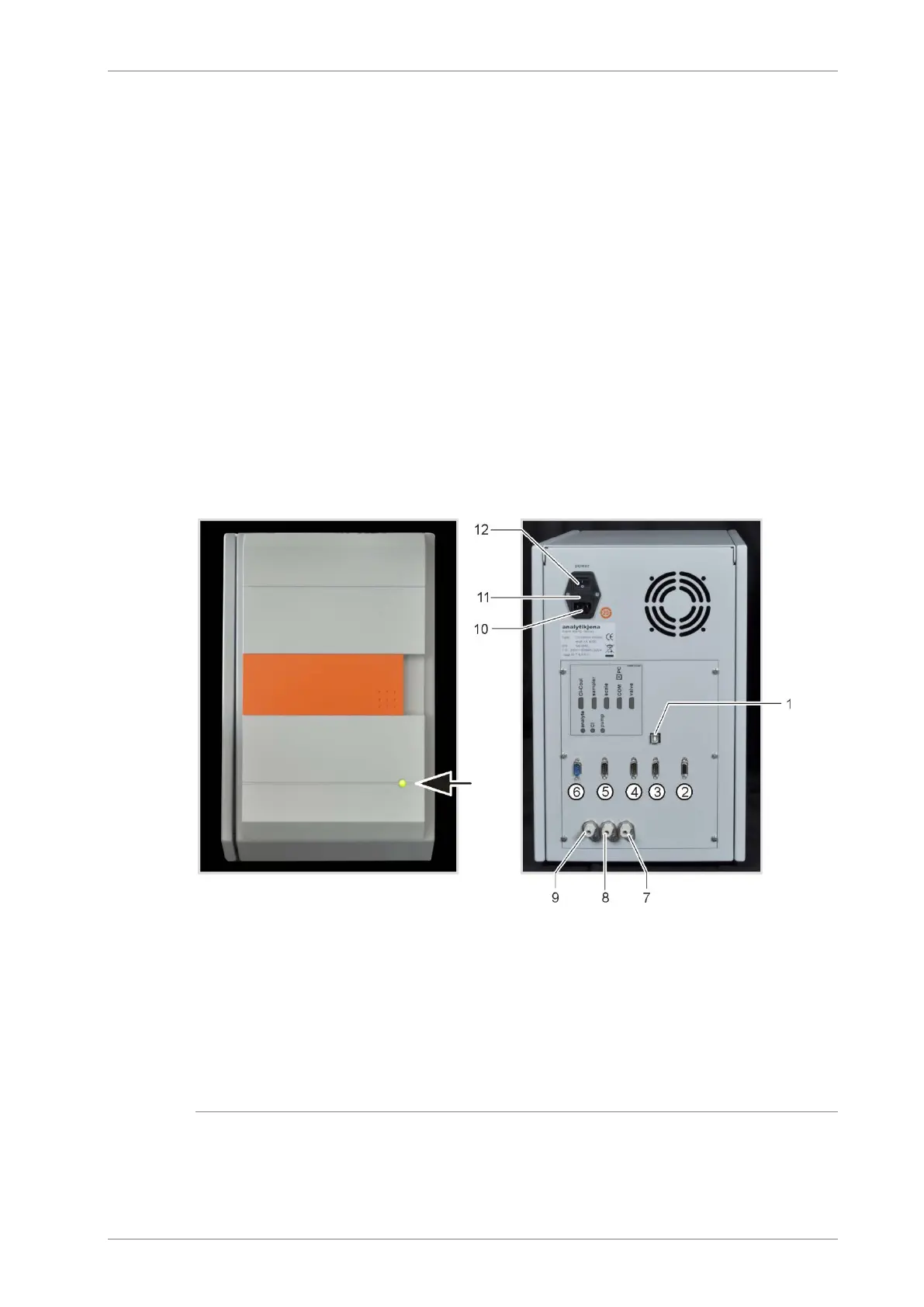
Connections
The green LED located at the front of the C/S module illuminates once the module has been
switched on. On the rear are the mains switch with mains input and fuse holder, the connec-
tions for attachment to the basic device and the additional add-on modules and the inlets
and outlets for the measuring flows.
1 USB connection "PC" for connecting the
computer
"valve" connection – connection to the
multi EA 4000
"COM" connection – connection to the
multi EA 4000
"scale" – connection of the scales
"sampler" connection – connection of the sampler
FPG 48
Cl-Coul – connection to the Cl module
7 gas outlet "pump" – connection to the multi EA
4000
gas connection "Cl" – connection to the Cl mod-
ule
gas inlet "analyte" – Measuring gas inlet
mains plug connection
fuse holder
mains switch
Fig. 9 Indictors and connections at the C/S module