System design
multi EA 4000 Version 01.16 25
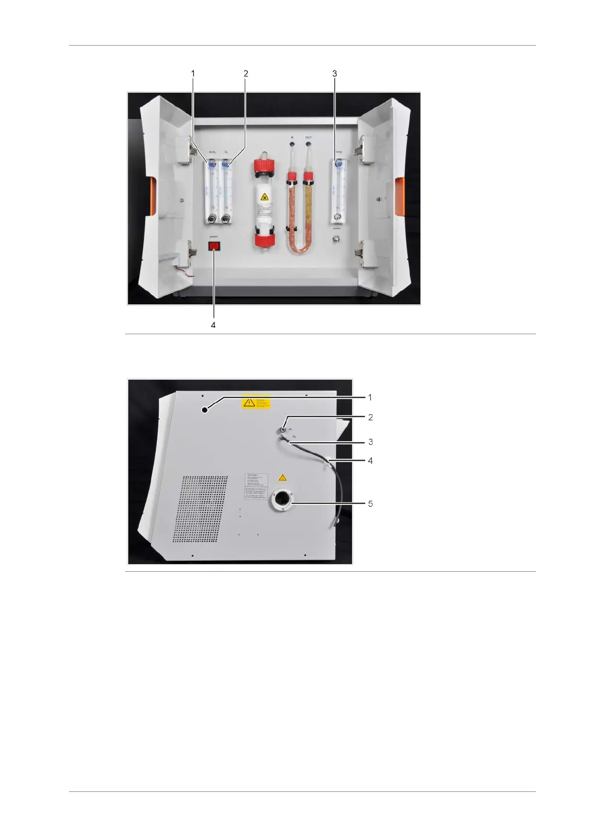
1 flow meter for control-
ling the argon or oxy-
gen flow "Ar/O
2
"
flow meter for control-
ling the oxygen flow
"O
2
"
flow meter for control-
ling the intake flow
"pump"
mains switch
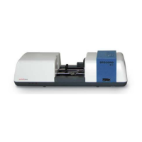
Fig. 6 Control elements behind the front doors of the multi EA 4000
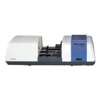
1 channel for measuring gas and by-
pass hoses during Cl measurements
connection "Ar" for the connection to
the combustion tube/gas airlock
connection "O
2
" for the connection to
the combustion tube/gas airlock/TIC
reactor
clip for securing the oxygen hose
opening of the combustion furnace
with airlock coupling for combustion
tubes
Fig. 7 Connections on the right-hand side of the multi EA 4000
On the rear of the multi EA 4000 are the gas inlets for the oxygen and argon supply, the
connections for the attachment to the C/S or Cl module and the mains connection cable.