Figures
multi EA 4000 Version 01.16 5
Index of Figures
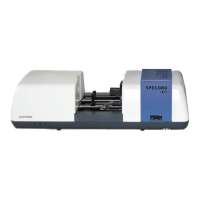
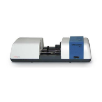
Fig. 1 Horizontal furnace of the basic device multi EA 4000 .......................................................... 22
Fig. 2 Flow meters at the basic device multi EA 4000 .................................................................... 23
Fig. 3 Dust trap at the combustion furnace .................................................................................... 23
Fig. 4 Drying tube and halide trap .................................................................................................. 24
Fig. 5 Status indicators at the basic device multi EA 4000 ............................................................. 24
Fig. 6 Control elements behind the front doors of the multi EA 4000 ............................................. 25
Fig. 7 Connections on the right-hand side of the multi EA 4000 .................................................... 25
Fig. 8 Connections on the rear of the multi EA 4000 ...................................................................... 26
Fig. 9 Indictors and connections at the C/S module ....................................................................... 27
Fig. 10 Cl module ............................................................................................................................. 28
Fig. 11 Layout of the measuring cell ................................................................................................ 29
Fig. 12 Combination electrode for measuring cell ............................................................................ 30
Fig. 13 Quartz combustion tube with gas airlock .............................................................................. 30
Fig. 14 Sulfuric acid containers for measuring gas drying ................................................................ 31
Fig. 15 Halide trap and adsorption tube in the Cl module ................................................................ 31
Fig. 16 Connections of the Cl module in combination with a C/S module ........................................ 32
Fig. 17 Connections for the coulometric cell at the inside panel of the Cl module ........................... 32
Fig. 18 Automatic TIC solids module................................................................................................ 33
Fig. 19 TIC reactor ........................................................................................................................... 34
Fig. 20 Hose pumps at the automatic TIC solids module ................................................................. 35
Fig. 21 Measuring gas drying and cleaning at the automatic TIC solids module .............................. 36
Fig. 22 Dust trap before the measuring gas inlet of the C/S module ................................................ 36
Fig. 23 Connections at the automatic TIC solids module ................................................................. 37
Fig. 24 Manual TIC solids module .................................................................................................... 38
Fig. 25 TIC reactor of the manual TIC solids module ....................................................................... 39
Fig. 26 Flow meter for oxygen flow .................................................................................................. 39
Fig. 27 Metering pump for acid at the manual TIC solids module .................................................... 40
Fig. 28 Components for measuring gas drying and cleaning at the manual TIC solids module ....... 41
Fig. 29 Connections at the manual TIC solids module ..................................................................... 41
Fig. 30 Checking the halide trap and drying tube ............................................................................. 54
Fig. 31 Individual components for the connection between the TIC reactor and ceramic tube ........ 71
Fig. 32 Hose connection at the halogen trap .................................................................................... 84
Fig. 33 Window STATUS ANALYZER .................................................................................................. 109
Fig. 34 Hose diagram for multi EA 4000 C/S ................................................................................. 123
Fig. 35 Hose diagram multi EA C/S for measurement in pyrolysis mode ....................................... 124
Fig. 36 Hose diagram multi EA Cl .................................................................................................. 126
Fig. 37 Hose diagram multi EA C/S Cl for C/S measurements with ceramic tube
and oxygen airlock ............................................................................................................. 128