Section 6 Correction Software
6-38
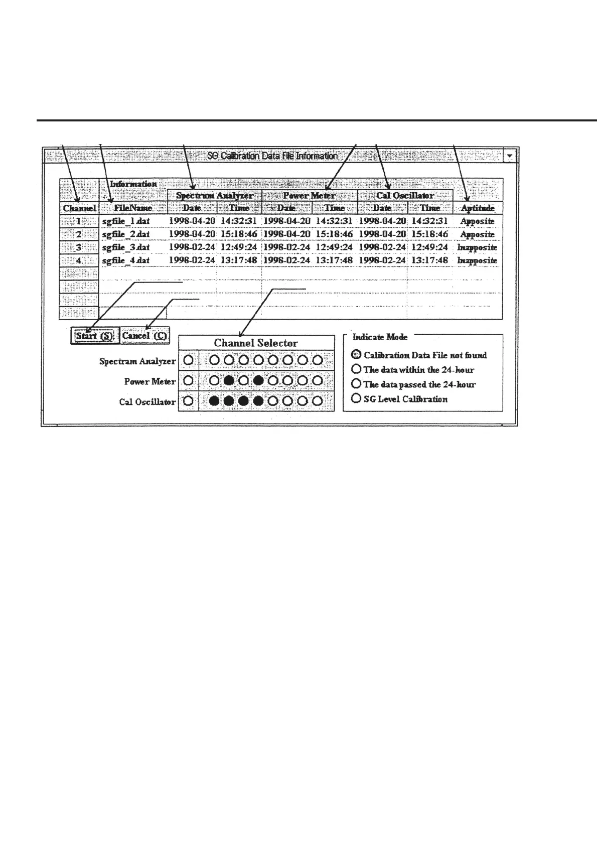
[1] [2] [3] [4] [5] [6]
[7]
[8]
[9]
Fig. 6-31 Signal Generator Calibration Selection Screen
Calibrate the level of the signal generator by following the instructions below.
(1) Set the reception system measurement on the “Initial Menu Screen” shown in
Fig. 6-4 and click the “Measure” button of section [15]. This causes the serial
number of the DUT and other data input prior to measurement start to be con-
firmed and the “Signal Generator Calibration Selection Screen” shown in Fig. 6-
31 to be displayed. Sections [3] to [5] display the date and time of creating data if
relevant data exist, or display “––––” in the absence of relevant data. Moreover,
the aptitude of usage of the data for measurement items selected on the “Initial
Menu Screen” shown in Fig. 6-4 is displayed in different colors in section [9].
(2) Select items to be calibrated. Double-clicking on the cell of sections [3] to [5]
displayed for each channel causes the relevant items in section [9] to switch into
blue, signifying that these items are selected. On the other hand, double-clicking
on the cell of sections [1], [2] and [6] causes calibration of all the data to be used
for each channel measurement to be selected.