Digital Video Recorder
5
CAUTION: The network connector is not designed to be connected directly with cable or
wire intended for outdoor use.
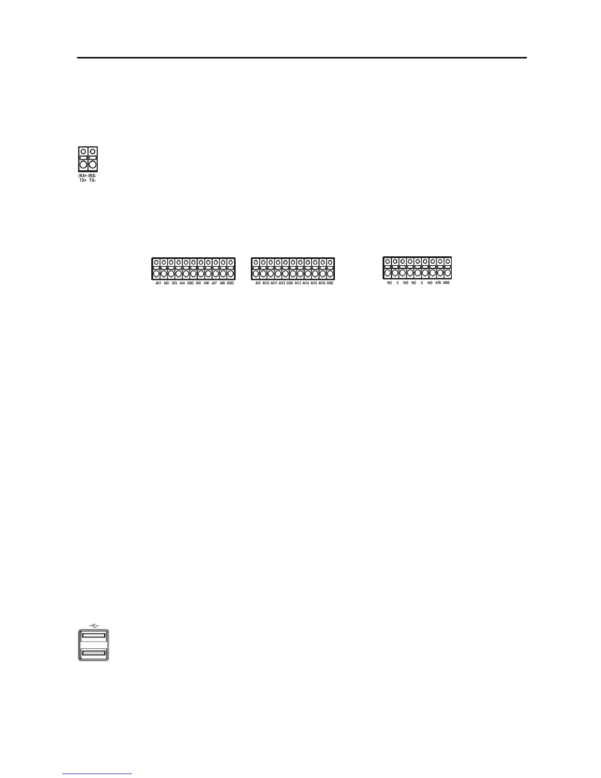
RS485 Port
Alarm Input/Output
NOTE: To make connections on the Alarm Connector Strip, press and hold the button and insert
the wire in the hole below the button. After releasing the button, tug gently on the wire to make
certain it is connected. To disconnect a wire, press and hold the button above the wire and pull
out the wire.
AI 1 to 16 (Alarm-In):
You can use external devices to signal the DVR to react to events. Mechanical or
electrical switches can be wired to the AI (Alarm-In) and GND (Ground) connectors. The threshold
voltage is 4.3V and should be stable at least 0.5 seconds to be detected. See Chapter 3 ─ Configuration
for configuring alarm input.
GND (Ground): Connect the ground side of the Alarm input and/or alarm output to the GND connector.
NOTE: All the connectors marked GND are common.
NC/NO (Relay Alarm Outputs): The DVR can activate external devices such as buzzers or lights.
Connect the device to the C (Common) and NC (Normally Closed) or C and NO (Normally Open)
connectors. NC/NO is a relay output which sinks 0.5A@125VAC and 1A@30VDC. See Chapter 3 ─
Configuration for configuring alarm output.
ARI (Alarm Reset In): An external signal to the Alarm Reset In can be used to reset both the Alarm
Out signal and the DVR’s internal buzzer. Mechanical or electrical switches can be wired to the ARI
(Alarm Reset In) and GND (Ground) connectors. The threshold voltage is below 0.3V and should be
stable at least 0.5 seconds to be detected. Connect the wires to the ARI (Alarm Reset In) and GND
(Ground) connectors.
USB Ports
A USB mouse (not supplied) can be connected to one of the ports. You can use the mouse to navigate
through the screens and menus much like you would on a computer.
The DVR can be controlled remotely by an external device or control system, such as a
control keyboard, using RS485 half-duplex serial communications signals. The RS485
connector can also be used to control PTZ (pan, tilt, zoom) cameras. Connect RX-/ TX- and
RX+/TX+ of the control system to the TX-/RX- and TX+/RX+ (respectively) of the DVR.
See Chapter 3 ─ Configuration and the PTZ camera or remote controller manufacture’s
manual for configuring the RS485 connection.
Two USB ports on the front panel are provided to connect external hard disk, CD-RW or
flash drives for video clip copying or system upgrades. Position external drives close
enough to the DVR so that you can make the cable connections, usually less than 6 feet. Use
the USB cable provided with the hard disk drive to connect it to the DVR.