DL205 User Manual, 4th Edition, Rev. D
3-24
Chapter 3: CPU Specifications and Operations
1
2
3
4
5
6
7
8
9
10
11
12
13
14
A
B
C
D
Bit Override — (DL240, DL250–1 and DL260) Bit override can be enabled on a point-by-
point basis by using AUX 59 from the Handheld Programmer or, by a menu option from
within DirectSOFT. Bit override basically disables any changes to the discrete point by the
CPU. For example, if you enable bit override for X1, and X1 is off at the time, then the CPU
will not change the state of X1. This means that even if X1 comes on, the CPU will not
acknowledge the change. So, if you used X1 in the program, it would always be evaluated as
“off” in this case. Of course, if X1 was on when the bit override was enabled, then X1 would
always be evaluated as “on.” There is an advantage available when you use the bit override
feature. The regular forcing is not disabled because the bit override is enabled. For example, if
you enabled the Bit Override for Y0 and it was off at the time, then the CPU would not change
the state of Y0. However, you can still use a programming device to change the status. Now, if
you use the programming device to force Y0 on, it will remain on and the CPU will not change
the state of Y0. If you then force Y0 off, the CPU will maintain Y0 as off. The CPU will never
update the point with the results from the application program or from the I/O update until
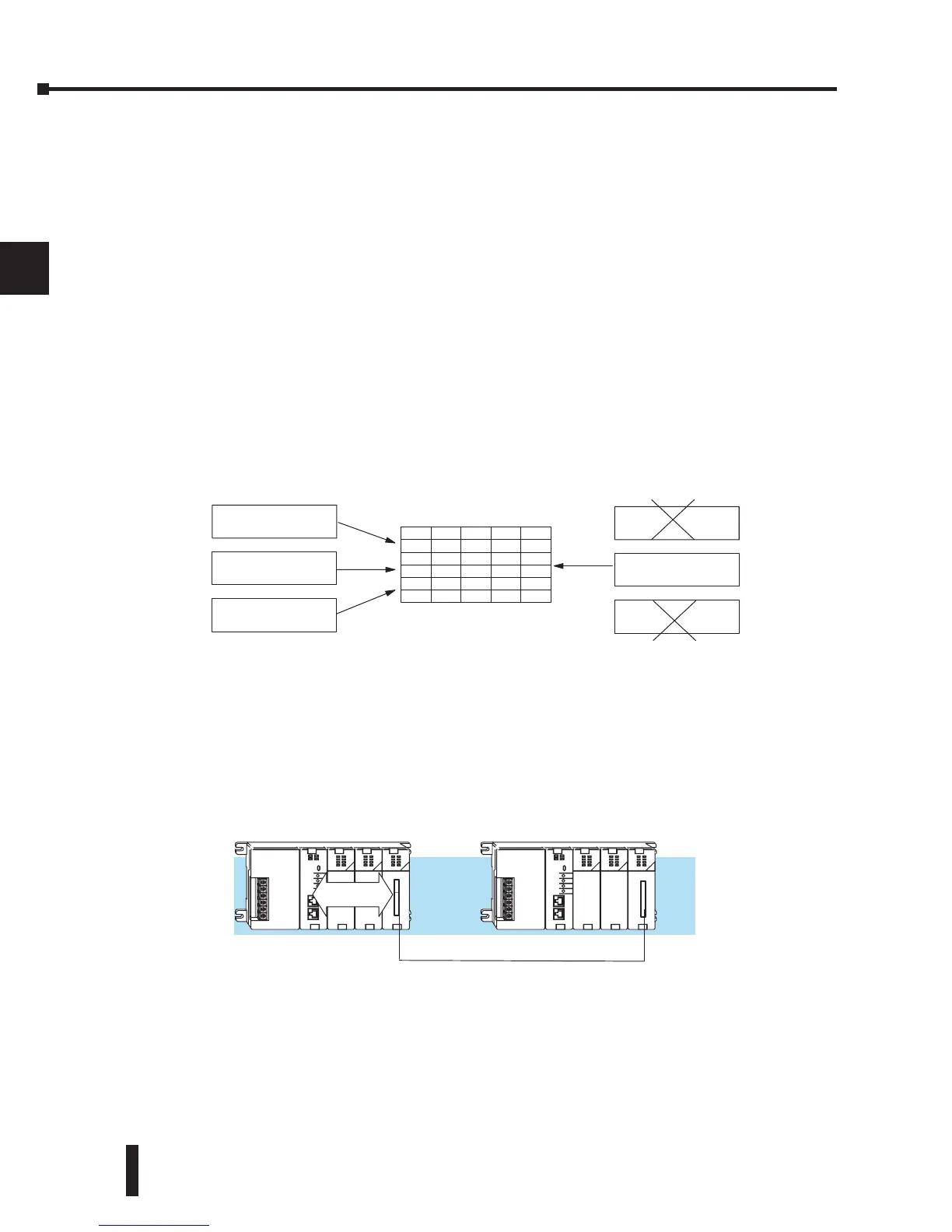
the bit override is removed. The following diagram shows a brief overview of the bit override
feature. Notice the CPU does not update the Image Register when bit override is enabled
CPU Bus Communication
Specialty Modules, such as the Data Communications Module, can transfer data to and from
the CPU over the CPU bus on the backplane. This data is more than standard I/O point
status. This type of communications can only occur on the CPU (local) base. A portion of the
execution cycle is used to communicate with these modules. The CPU performs both read and
write requests during this segment.
Update Clock, Special Relays and Special Registers
The DL240 , DL250–1 and DL260 CPUs have an internal real-time clock and calendar
timer which are accessible to the application program. Special V-memory locations hold this
information. This portion of the execution cycle makes sure these locations get updated on
every scan. Several different Special Relays, such as diagnostic relays, etc., are also updated
during this segment.
Input Update
Result of Program
Solution
OFF
Image Register (example)
Y1
Y2...Y128
ON
ON...OFF
C0C1C2...C377
OFFOFFON...OFF
Y0
OFF
X1
X2...X128
ON
ON...OFF
X0
Bit Override OFF
Force from
Programmer
Input Update
Result of Program
Solution
Bit Override ON
Force from
Programmer