DL205 User Manual, 4th Edition, Rev. D
2-26
Chapter 2: Installation, Wiring and Specifications
1
2
3
4
5
6
7
8
9
10
11
12
13
14
A
B
C
D
I/O Modules Position, Wiring, and Specification
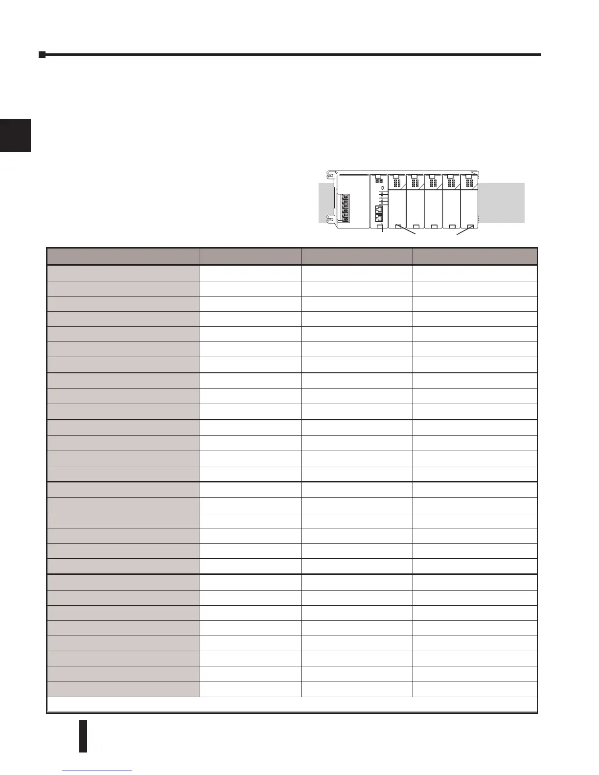
Slot Numbering
The DL205 bases each provide different numbers of slots for use with the I/O modules. You
may notice the bases refer to 3-slot, 4-slot, etc. One of the slots is dedicated to the CPU, so
you always have one less I/O slot. For example, you have five I/O slots with a 6-slot base. The
I/O slots are numbered 0–4. The CPU slot always contains a PLC CPU or other CPU–slot
controller and is not numbered.
Module Placement Restrictions
The following table lists the valid locations for
all types of modules in a DL205 system:
Module/Unit Local CPU Base Local Expansion Base Remote I/O Base
CPUs
CPU Slot Only
DC Input Modules .
A A A
AC Input Modules
A A A
DC Output Modules
A A A
AC Output Modules
A A A
Relay Output Modules
A A A
Analog Input and Output Modules
A A A
Local Expansion
Base Expansion Module
A A
Base Controller Module
CPU Slot Only
Serial Remote I/O
Remote Master
A
Remote Slave Unit
CPU Slot Only
Ethernet Remote Master
A
CPU Interface
Ethernet Base Controller
Slot 0 Only Slot 0 Only*
WinPLC
Slot 0 Only
DeviceNet
Slot 0 Only
Profibus
Slot 0 Only
SDS
Slot 0 Only
Specialty Modules
Counter Interface
Slot 0 Only
Counter I/O
A
A*
Data Communications
A
Ethernet Communications
A
BASIC CoProcessor
A
Simulator
A A A
Filler
A A A
* When used with H2-ERM(100) Ethernet Remote I/O system