DL205 User Manual, 4th Edition, Rev. D
3-23
Chapter 3: CPU Specifications and Operations
1
2
3
4
5
6
7
8
9
10
11
12
13
14
A
B
C
D
Read Inputs
The CPU reads the status of all inputs, then stores it in the image register. Input image register
locations are designated with an X followed by a memory location. Image register data is used
by the CPU when it solves the application program. Of course, an input may change after
the CPU has read the inputs. Generally, the CPU scan time is measured in milliseconds. If
you have an application that cannot wait until the next I/O update, you can use Immediate
Instructions. These do not use the status of the input image register to solve the application
program. The Immediate instructions immediately read the input status directly from I/O
modules. However, this lengthens the program scan since the CPU has to read the I/O point
status again. A complete list of the Immediate instructions is included in Chapter 5.
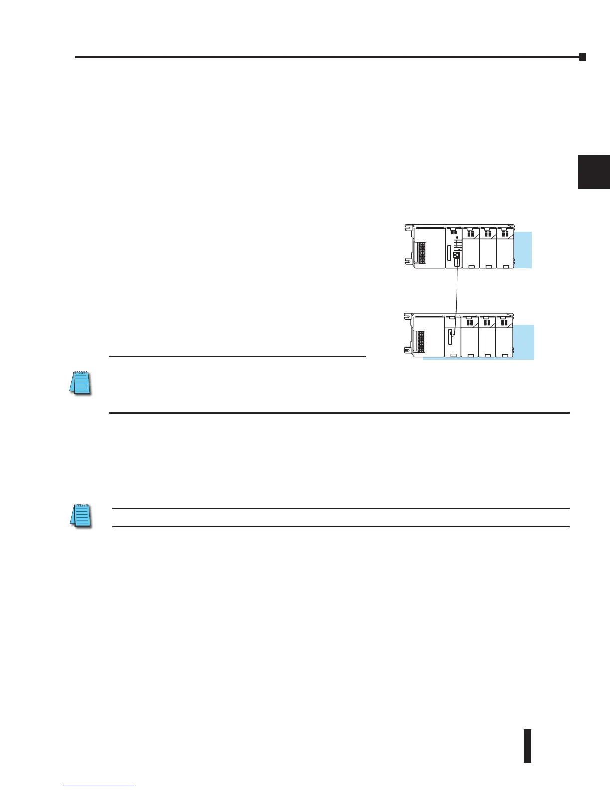
Read Inputs from Specialty and Remote I/O
After the CPU reads the inputs from the input
modules, it reads any input point data from any
Specialty modules that are installed, such as Counter
Interface modules, etc. This is also the portion of
the scan that reads the input status from Remote I/O
bases.
NOTE: It may appear the Remote I/O point status is
updated every scan. This is not quite true. The CPU will receive information from the Remote I/O Master
module every scan, but the Remote Master may not have received an update from all the Remote Slaves.
Remember, the Remote I/O link is managed by the Remote Master, not the CPU.
Service Peripherals and Force I/O
After the CPU reads the inputs from the input modules, it reads any attached peripheral
devices. This is primarily a communications service for any attached devices. For example,
it would read a programming device to see if any input, output, or other memory type status
needs to be modified. Two basic types of forcing are available with the DL205 CPUs.
NOTE: DirectNet protocol does not support bit operations.
• Forcing from a peripheral – not a permanent force, good only for one scan
• Bit Override (DL240, DL250–1 and DL260) – holds the I/O point (or other bit) in the current
state. Valid bits are X, Y, C, T, CT, and S. These memory types are discussed in more detail later
in this chapter.
Regular Forcing — This type of forcing can temporarily change the status of a discrete bit.
For example, you may want to force an input on, even though it is really off. This allows you
to change the point status that was stored in the image register. This value will be valid until
the image register location is written to during the next scan. This is primarily useful during
testing situations when you need to force a bit on to trigger another event.
___
___
DL250–1/260
RSSS