DL205 User Manual, 4th Edition, Rev. D
3-40
Chapter 3: CPU Specifications and Operations
1
2
3
4
5
6
7
8
9
10
11
12
13
14
A
B
C
D
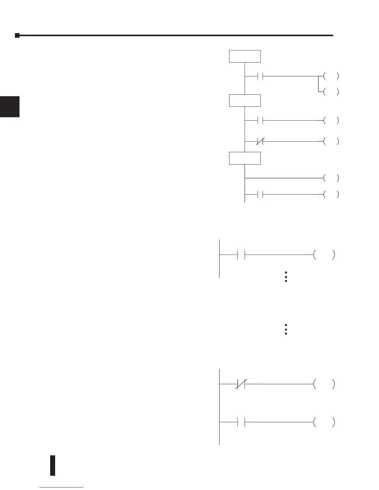
Stages (S Data type)
Stages are used in RLL
PLUS
programs to create a
structured program, similar to a flowchart. Each
program stage denotes a program segment. When
the program segment, or stage, is active, the logic
within that segment is executed. If the stage is
off, or inactive, the logic is not executed and the
CPU skips to the next active stage. (See Chapter
7 for a more detailed description of RLL
PLUS
programming.)
Each stage also has a discrete status bit that can be
used as an input to indicate whether the stage is
active or inactive. If the stage is active, then the
status bit is on. If the stage is inactive, then the
status bit is off. This status bit can also be turned
on or off by other instructions, such as the SET
or RESET instructions. This allows you to easily
control stages throughout the program.
Special Relays (SP Data Type)
Special relays are discrete memory locations
with pre-defined functionality. There are many
different types of special relays. For example,
some aid in program development, others
provide system operating status information, etc.
Appendix D provides a complete listing of the
special relays.
In this example, control relay C10 will energize
for 50ms and de–energize for 50 ms because SP5
is a pre–defined relay that will be on for 50ms and
off for 50ms.
Remote I/O Points (GX Data Type)
Remote I/O points are represented by global
relays. They are generally used only to control
remote I/O, but they can be used as normal
control relays when remote I/O is not used in the
system.
In this example, memory location GX0 represents
an output point and memory location GX10
represents an input point.