DL205 User Manual, 4th Edition, Rev. D
2-14
Chapter 2: Installation, Wiring and Specifications
1
2
3
4
5
6
7
8
9
10
11
12
13
14
A
B
C
D
I/O Wiring Strategies
The DL205 PLC system is very flexible and will work in many different wiring configurations.
By studying this section before actual installation, you can probably find the best wiring
strategy for your application. This will help to lower system cost, wiring errors, and avoid
safety problems.
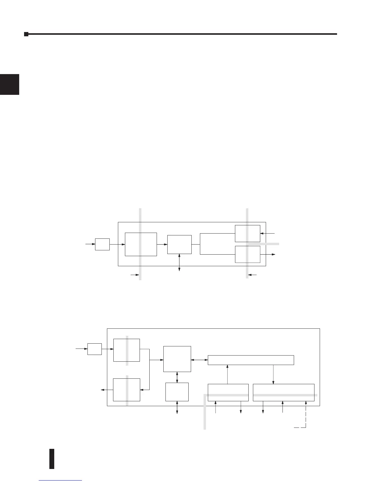
PLC Isolation Boundaries
PLC circuitry is divided into three main regions separated by isolation boundaries, shown in
the drawing below. Electrical isolation provides safety, so that a fault in one area does not
damage another. A powerline filter will provide isolation between the power source and the
power supply. A transformer in the power supply provides magnetic isolation between the
primary and secondary sides. Opto-couplers provide optical isolation in Input and Output
circuits. This isolates logic circuitry from the field side, where factory machinery connects.
Note the discrete inputs are isolated from the discrete outputs, because each is isolated from the
logic side. Isolation boundaries protect the operator interface (and the operator) from power
input faults or field wiring faults. When wiring a PLC, it is extremely important to avoid
making external connections that connect logic side circuits to any other.
In addition to the basic circuits covered above, AC-powered and 125VDC bases include an
auxiliary +24VDC power supply with its own isolation boundary. Since the supply output is
isolated from the other three circuits, it can power input and/or output circuits!