DL205 User Manual, 4th Edition, Rev. D
4-19
Chapter 4: System Design and Configuration
1
2
3
4
5
6
7
8
9
10
11
12
13
14
A
B
C
D
Installing the ERM Module
This section will briefly describe the installation of the ERM module. More detailed
information is available in the Ethernet Remote Master Module manual, H24-ERM-M, which
will be needed to configure the communication link to the remote I/O.
In addition to the manual, configuration software will be needed. The ERM Workbench
software utility must be used to configure the ERM and its slave modules. The utility is
provided on a CD which comes with the ERM manual. The ERM module can be identified by
two different methods, either by Module ID (dip switch) or by Ethernet address. Whichever
method is used, the ERM Workbench is all that is needed to configure the network modules.
If IP addressing (UDP/IP) is necessary or if the Module ID is set with software, the NetEdit
software utility (included with the ERM Workbench utility) will be needed in addition to the
ERM Workbench.
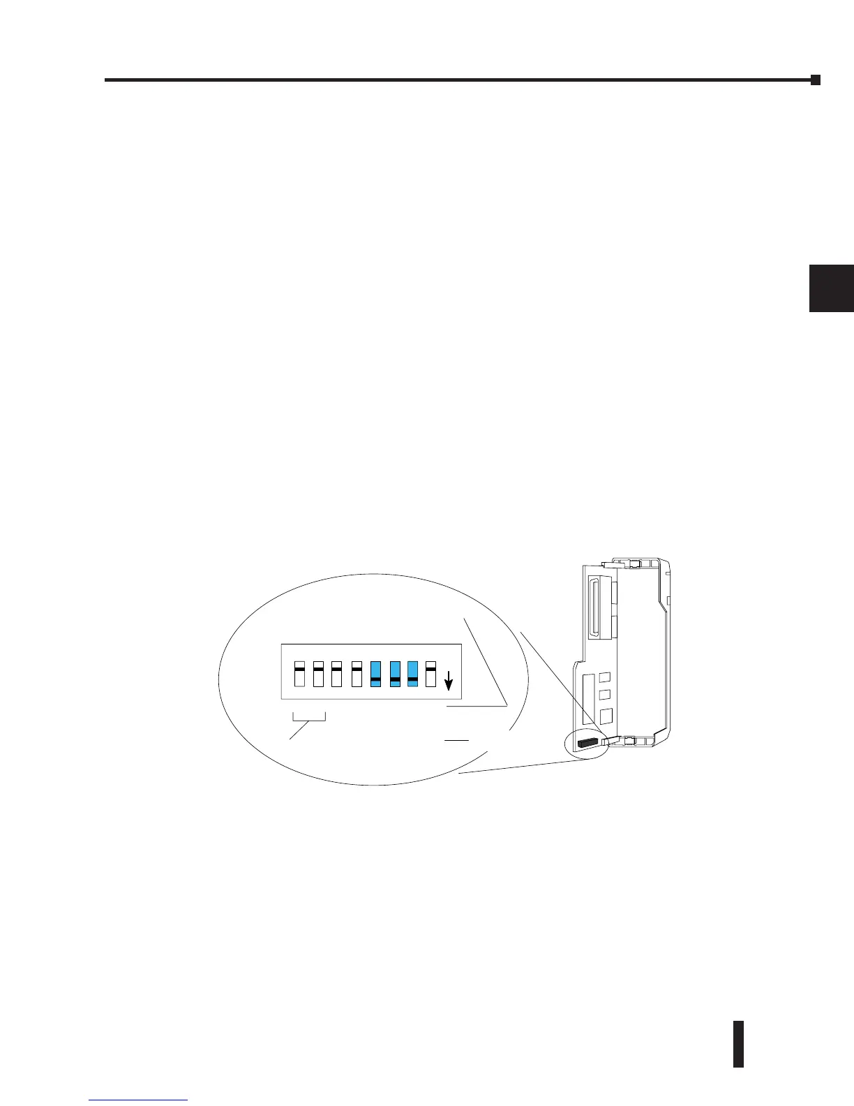
ERM Module ID
Set the ERM Module ID before installing the module in the DL205 base. Always set the
module ID to 0. A Module ID can be set in one of two ways:
• Use the DIP switches on the module (1-63)
• Use the configuration tools in NetEdit
Use the DIP switch to install and change slave modules without using a PC to set the Module
ID. Set the module’s DIP switch, insert the module in the base, and connect the network
cable. The Module ID is set on power up, and it is ready to communicate on the network.
The Module IDs can also be set or changed on the network from a single PC by using the tools
in NetEdit.
The Module ID equals the sum of the binary values of the slide switches set in the ON position.
For example, if slide switches 1, 2 and 3 are set to the ON position, the Module ID will be 14.
This is found by adding 8+4+2=14. The maximum value which can be set on the DIP switch
is 32+16+8+4+2=63. This is achieved by setting switches 0 through 5 to the ON position. The
6 and 7 switch positions are inactive.