DL205 User Manual, 4th Edition, Rev. D
2-27
Chapter 2: Installation, Wiring and Specifications
1
2
3
4
5
6
7
8
9
10
11
12
13
14
A
B
C
D
Special Placement Considerations for Analog Modules
In most cases, the analog modules can be placed in any slot. However, the placement can
also depend on the type of CPU you are using and the other types of modules installed to the
left of the analog modules. If you’re using a DL230 CPU (or a DL240 CPU with firmware
earlier than V1.4) you should check the DL205 Analog I/O Manual for any possible placement
restrictions related to your particular module. You can order the DL205 Analog I/O Manual
by ordering part number D2–ANLG–M.
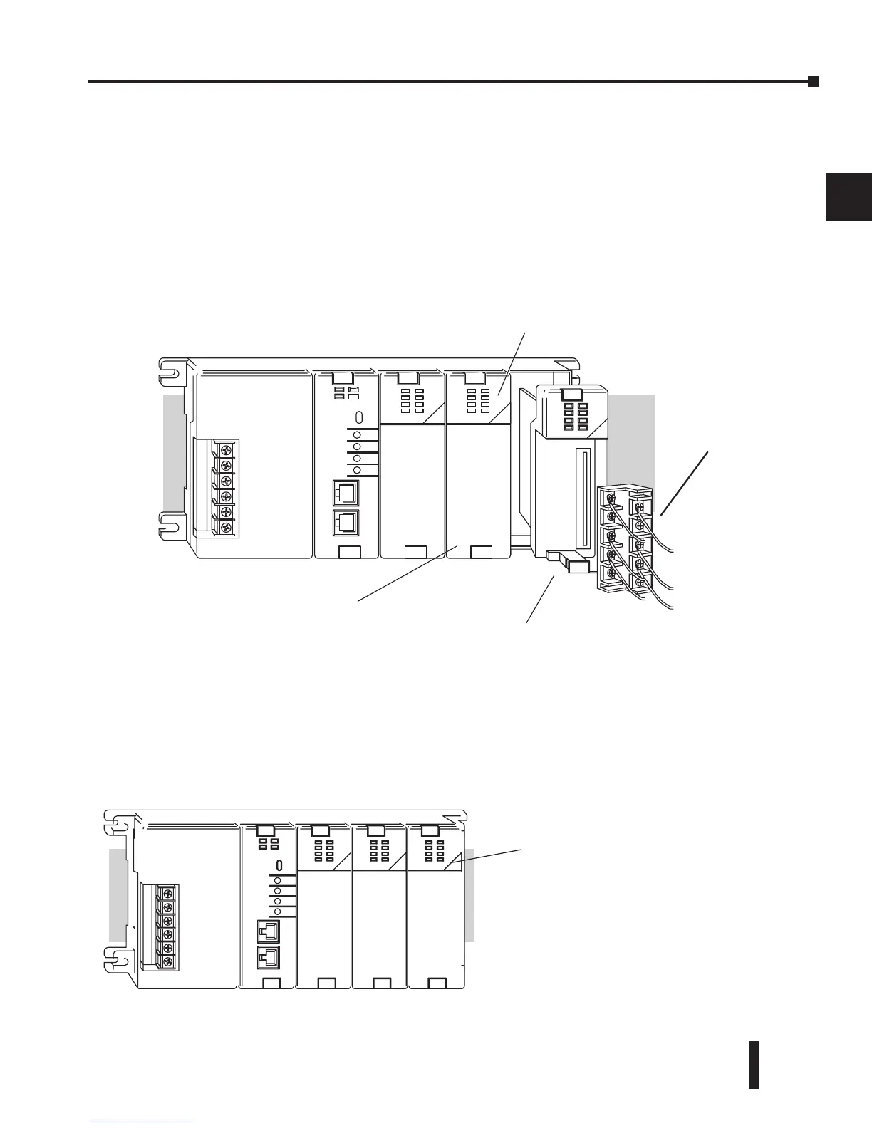
Discrete Input Module Status Indicators
The discrete modules provide LED status indicators to show the status of the input points.
Color Coding of I/O Modules
The DL205 family of I/O modules have a color coding scheme to help you quickly identify if a
module is either an input module, output module, or a specialty module. This is done through
a color bar indicator located on the front of each module. The color scheme is listed below:
Wire tray area