DL205 User Manual, 4th Edition, Rev. D
3-41
Chapter 3: CPU Specifications and Operations
1
2
3
4
5
6
7
8
9
10
11
12
13
14
A
B
C
D
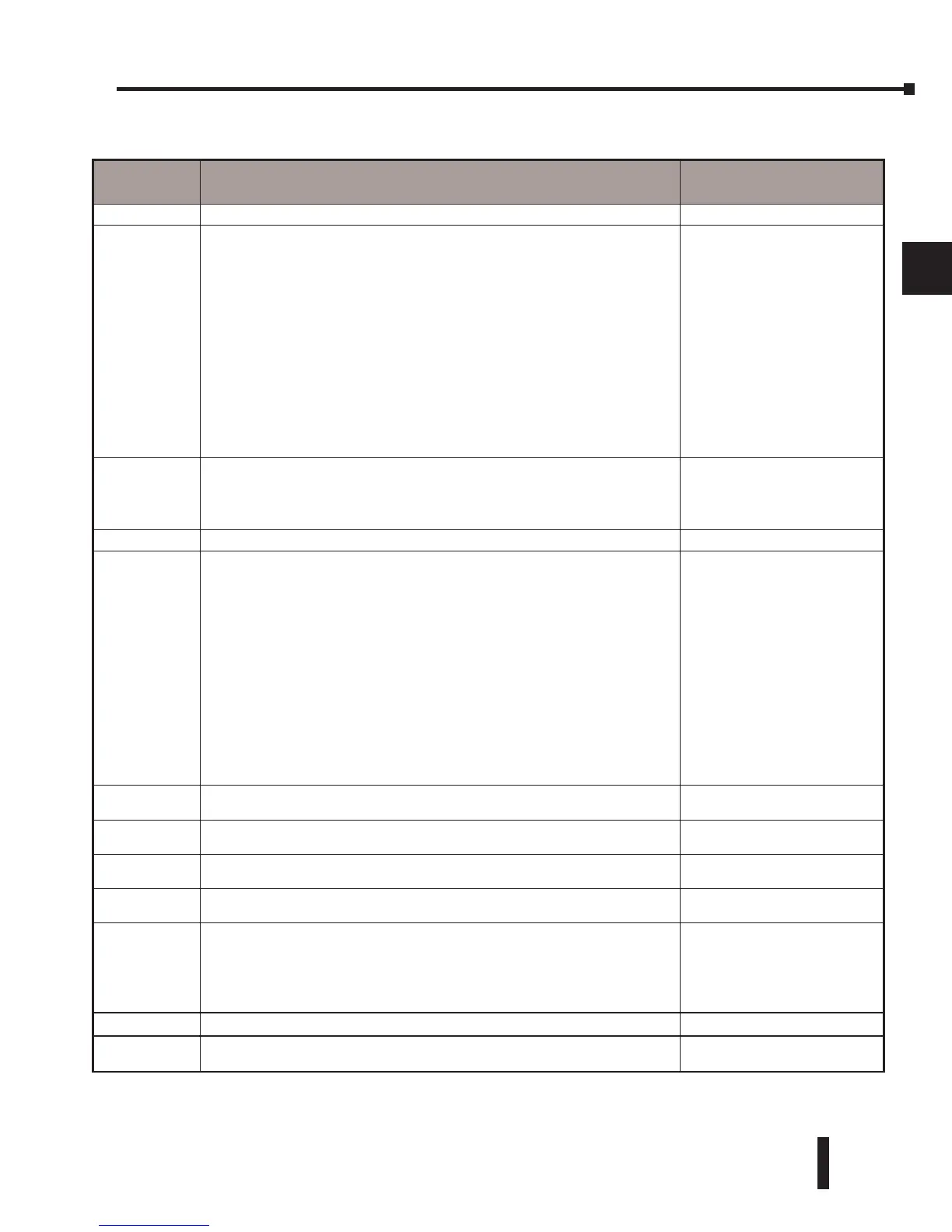
DL230 System V-memory
System
V-memory
Description of Contents Default Values/Ranges
V2320–V2377 The default location for multiple preset values for the UP counter. N/A
V7620–V7627
V7620
V7621
V7622
V7623
V7624
V7625
V7626
V7627
Locations for DV–1000 operator interface parameters
Sets the V-memory location that contains the value.
Sets the V-memory location that contains the message.
Sets the total number (1 - 16) of V-memory locations to be displayed.
Sets the V-memory location that contains the numbers to be displayed.
Sets the V-memory location that contains the character code to be displayed.
Sets the bit control pointer.
Power Up mode change preset value password.
Reserved for future use.
V0–V2377
V0–V2377
1–16
V0–V2377
V0–V2377
V-memory location for
X,Y, or C points used.
0,1,2,3,12 Default = 0000
V7630
Starting location for the multi–step presets for channel 1. The default value is
2320, which indicates the first value should be obtained from V2320. Since 24
presets are available, the default range is V2320 – V2377. You can change the
starting point if necessary.
Default: V2320
Range: V0–V2320
V7631–V7632 Not used N/A
V7633 Sets the desired mode for the high speed counter, interrupt, pulse catch,
pulse train, and input filter (see the D2-CTRINT Manual, D2-CTRIF-M for more
information). Location is also used for setting the with/without battery option,
enable/disable CPU mode change, and power-up in Run Mode option.
Default: 0000
Lower Byte Range:
Range: 0–None
10–Up
40–Interrupt
50–Pulse Catch
60–Filtered discrete In.
Upper Byte Range:
Bits 8–11, 14,15: Unused
Bit 12: With Batt. installed:
0 = disable BATT LED
1 = enable BATT LED
Bit 13: Power-up in Run
V7634
Contains set-up information for high-speed counter, interrupt, pulse catch,
pulse train output, and input filter for X0 (when D2–CTRINT is installed).
Default: 0000
V7635
Contains set up-information for high-speed counter, interrupt, pulse catch,
pulse train output, and input filter for X1 (when D2–CTRINT is installed).
Default: 0000
V7636
Contains set-up information for high-speed counter, interrupt, pulse catch,
pulse train output, and input filter for X2 (when D2–CTRINT is installed).
Default: 0000
V7637
Contains set-up information for high-speed counter, interrupt, pulse catch,
pulse train output, and input filter for X3 (when D2–CTRINT is installed).
Default: 0000
V7640–V7642
V7640
V7641
V7642
Additional setup parameters for the DV-1000
Timer preset value pointer
Counter preset value pointer
Timer preset block size (high byte) / Counter preset block size (low byte)
V2000–V2377
V2000–V2377
1–99
V7643–V7647 Not used N/A
V7751
Fault Message Error Code — stores the 4-digit code used with the FAULT
instruction when the instruction is executed.
N/A