DL205 User Manual, 4th Edition, Rev. D
4-6
Chapter 4: System Design and Configuration
1
2
3
4
5
6
7
8
9
10
11
12
13
14
A
B
C
D
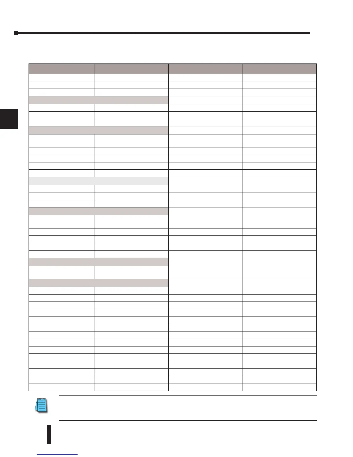
I/O Points Required for Each Module
Each type of module requires a certain number of I/O points. This is also true for some
specialty modules, such as analog, counter interface, etc.
NOTE: 12pt. modules consume 16 points. The first 6 points are assigned, two are skipped, and then the
next 6 points are assigned. For example, a D2–12TA installed in slot 0 would use Y0–Y5, and Y-10-Y15.
Y6–Y7 and Y16–Y17 would be unused.
DC Input Modules Number of I/O Pts. Required Specialty Modules, etc. Number of I/O Pts. Required
D2–08ND3 8 Input H2–ECOM(–F) None
D2–16ND3–2 16 Input D2–DCM None
D2–32ND3(–2) 32 Input H2–ERM(100,–F) None
AC Input Modules
H2–EBC(–F) None
D2–08NA–1 8 Input D2–RMSM None
D2–08NA–2 8 Input D2–RSSS None
D2–16NA 16 Input F2–CP128 None
DC Output Modules
H2–CTRIO(2) None
D2–04TD1
8 Output (Only the first four
points are used)
D2–CTRINT 8 Input 8 Output
D2–08TD1 8 Output F2–DEVNETS–1 None
D2–16TD1–2 (2-2) 16 Output H2–PBC None
D2–16TD1(2)P 16 Output F2–SDS–1 None
D2–32TD1(–2) 32 Output D2–08SIM 8 Input
AC Output Modules
D2-EM None
D2–08TA 8 Output D2-CM None
F2–08TA 8 Output H2-ECOM(100) None
D2–12TA 16 Output (See note 1)
Relay Output Modules
D2–04TRS
8 Output (Only the first four
points are used)
D2–08TR 8 Output
F2–08TRS 8 Output
F2–08TR 8 Output
D2–12TR 16 Output (See note 1)
Combination Modules
D2–08CDR
8 In, 8 Out (Only the first four
points are used for each type)
Analog Modules
F2–04AD–1 & 1L 16 Input
F2–04AD–2 & 2L 16 Input
F2–08AD–1 16 Input
F2–02DA–1 & 1L 16 Output
F2–02DA–2 & 2L 16 Output
F2–08DA–1 16 Output
F2–08DA–2 16 Output
F2–02DAS–1 32 Output
F2–02DAS–2 32 Output
F2–4AD2DA 16 Input & 16 Output
F2–8AD4DA-1 32 Input & 32 Output
F2–8AD4DA-2 32 Input & 32 Output
F2–04RTD 32 Input
F2–04THM 32 Input