DL205 User Manual, 4th Edition, Rev. D
3-19
Chapter 3: CPU Specifications and Operations
1
2
3
4
5
6
7
8
9
10
11
12
13
14
A
B
C
D
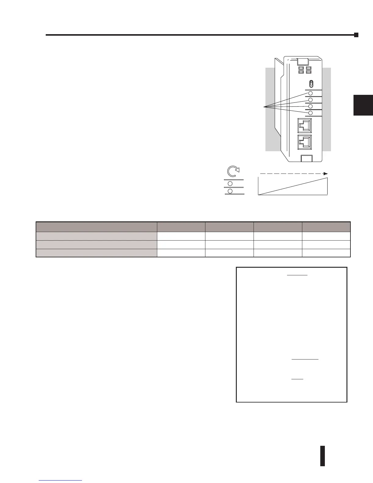
Setting the Analog Potentiometer Ranges
Four analog potentiometers (pots) are on the
face plate of the DL240 CPU. These pots can
be used to change timer constants, frequency of
pulse train output, value for an analog output
module, etc.
Each analog channel has corresponding
V-memory locations for setting lower and upper
limits for each analog channel.
To increase the value associated with the analog
pot, turn the pot clockwise. To decrease the
value, turn the pot counter clockwise
The table below shows the V-memory locations
used for each analog channel. These are the
default locations for the analog pots.
You can use the program logic to load the limits
into these locations, or, you can use a programming
device to load the values. The range for each limit
is 0 – 9999.
These analog pots have a resolution of 256 pieces.
Therefore, if the span between the upper and lower
limits is less than or equal to 256, then you have
better resolution or, more precise control.
Use the formula shown to determine the smallest
amount of change that can be detected.
For example, a range of 100 – 600 would result in a
resolution of 1.95. Therefore, the smallest increment
would be 1.95 units. (The actual result depends on
exactly how you are using the values in the control
program).
CH1 CH2 CH3 CH4
Analog Data
V3774 V3775 V3776 V3777
Analog Data Lower Limit
V7640 V7642 V7644 V7646
Analog Data Upper Limit
V7641 V7643 V7645 V7647