DL205 User Manual, 4th Edition, Rev. D
4-9
Chapter 4: System Design and Configuration
1
2
3
4
5
6
7
8
9
10
11
12
13
14
A
B
C
D
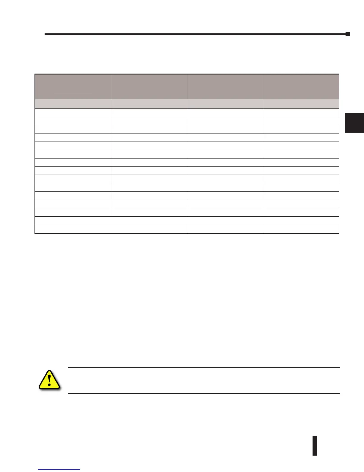
Power Budget Calculation Example
The following example shows how to calculate the power budget for the DL205 system.
1. Use the power budget table to fill in the power requirements for all the system components.
First, enter the amount of power supplied by the base. Next, list the requirements for
the CPU, any I/O modules, and any other devices, such as the Handheld Programmer,
C-more HMI or the DV–1000 operator interface. Remember, even though the Handheld
Programmer or the DV–1000 are not installed in the base, they still obtain their power
from the system. Also, make sure you obtain any external power requirements, such as the
24VDC power required by the analog modules.
2. Add the current columns starting with CPU slot and put the total in the row labeled “Total
Power Required.”
3. Subtract the row labeled “Total Power Required” from the row labeled “Available Base
Power.” Place the difference in the row labeled “Remaining Power Available.”
4. If “Total Power Required” is greater than the power available from the base, the power
budget will be exceeded. It will be unsafe to use this configuration, and you will need to
restructure your I/O configuration.
WARNING: It is extremely important to calculate the power budget. If you exceed the power budget,
the system may operate in an unpredictable manner which may result in a risk of personal injury or
equipment damage.
Base #
0
Module Type 5 VDC (mA)
Auxiliary
Power Source
24 VDC Output (mA)
Available Base Power D2–09B–1 2600 300
CPU Slot D2–260 + 330
Slot 0 D2–16ND3–2 + 100 + 0
Slot 1 D2–16NA + 100 + 0
Slot 2 D2–16NA + 100 + 0
Slot 3 F2–04AD–1 + 50 + 80
Slot 4 F2–02DA–1 + 40 + 60
Slot 5 D2–08TA + 250 + 0
Slot 6 D2–08TD1 + 100 + 0
Slot 7 D2–08TR + 250 + 0
Other
Handheld Programmer D2–HPP + 200 + 0
Total Power Required 1520 140
Remaining Power Available 2600–1520 = 1080 300 – 140 = 160