DL205 User Manual, 4th Edition, Rev. D
2-21
Chapter 2: Installation, Wiring and Specifications
1
2
3
4
5
6
7
8
9
10
11
12
13
14
A
B
C
D
Relay Output Guidelines
Several output modules in the DL205 I/O family feature relay outputs: D2–04TRS, D2–08TR,
D2–12TR, D2–08CDR, F2–08TR and F2–08TRS. Relays are best for the following
applications:
• Loads that require higher currents than the solid-state outputs can deliver
• Cost-sensitive applications
• Some output channels need isolation from other outputs (such as when some loads require different
voltages than other loads)
Some applications in which NOT to use relays:
• Loads that require currents under 10 mA
• Loads which must be switched at high speed or heavy duty cycle
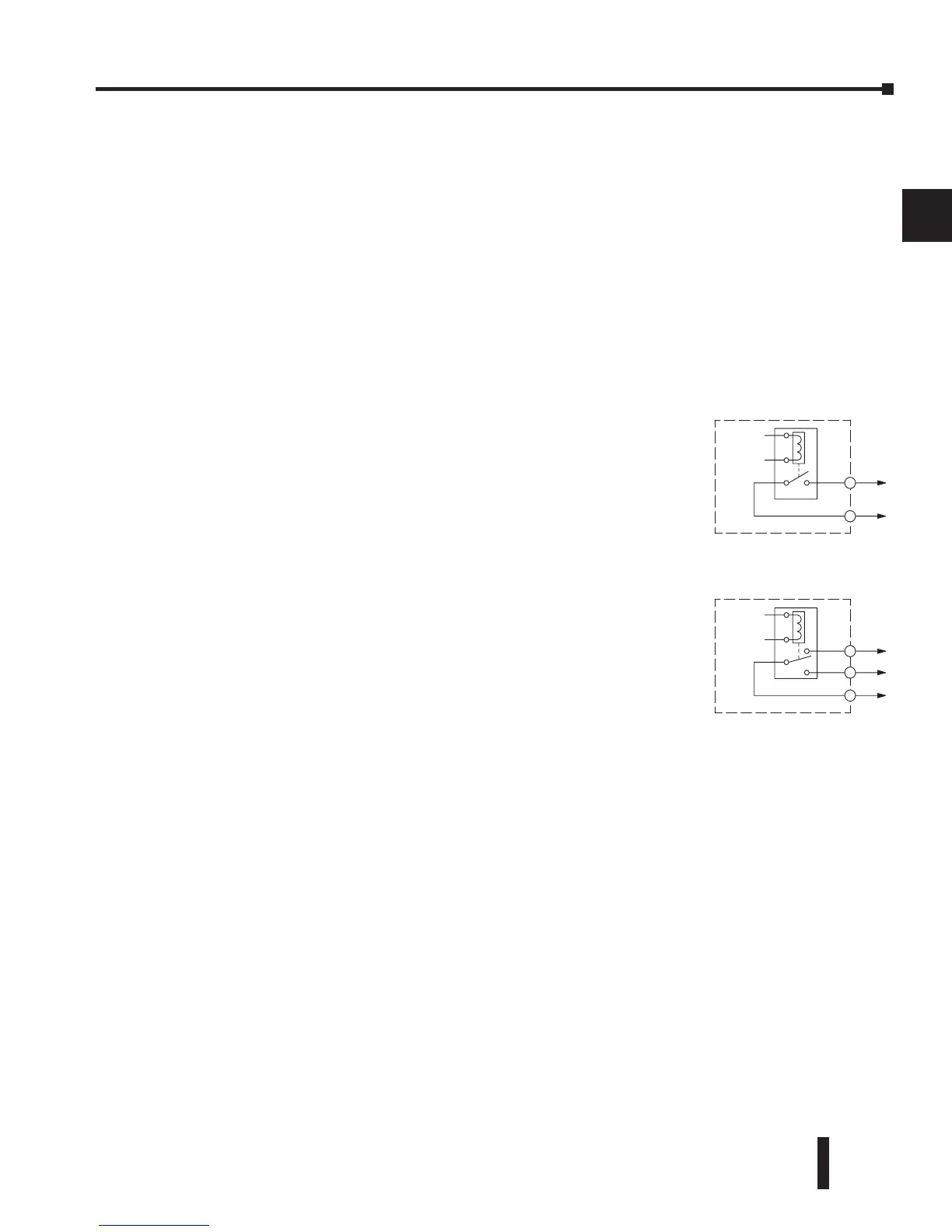
Relay outputs in the DL205 output modules are available in two
contact arrangements, shown to the right. The Form A type, or
SPST (single pole, single throw) type is normally open and is the
simplest to use. The Form C type, or SPDT (single pole, double
throw) type has a center contact which moves and a stationary
contact on either side. This provides a normally closed contact
and a normally open contact.
Some relay output module’s relays share common terminals,
which connect to the wiper contact in each relay of the bank.
Other relay modules have relays which are completely isolated
from each other. In all cases, the module drives the relay coil
when the corresponding output point is on.
Relay Outputs – Transient Suppression for Inductive Loads in a Control System
The following pages are intended to give a quick overview of the negative effects of transient
voltages on a control system and provide some simple advice on how to effectively minimize
them. The need for transient suppression is often not apparent to the newcomers in the
automation world. Many mysterious errors that can afflict an installation can be traced back
to a lack of transient suppression.
What is a Transient Voltage and Why is it Bad?
Inductive loads (devices with a coil) generate transient voltages as they transition from being
energized to being de-energized. If not suppressed, the transient can be many times greater
than the voltage applied to the coil. These transient voltages can damage PLC outputs or other
electronic devices connected to the circuit, and cause unreliable operation of other electronics
in the general area. Transients must be managed with suppressors for long component life and
reliable operation of the control system.
This example shows a simple circuit with a small 24V/125mA/3W relay. As you can see, when
the switch is opened, thereby de-energizing the coil, the transient voltage generated across the
switch contacts peaks at 140V.