DL205 User Manual, 4th Edition, Rev. D
2-20
Chapter 2: Installation, Wiring and Specifications
1
2
3
4
5
6
7
8
9
10
11
12
13
14
A
B
C
D
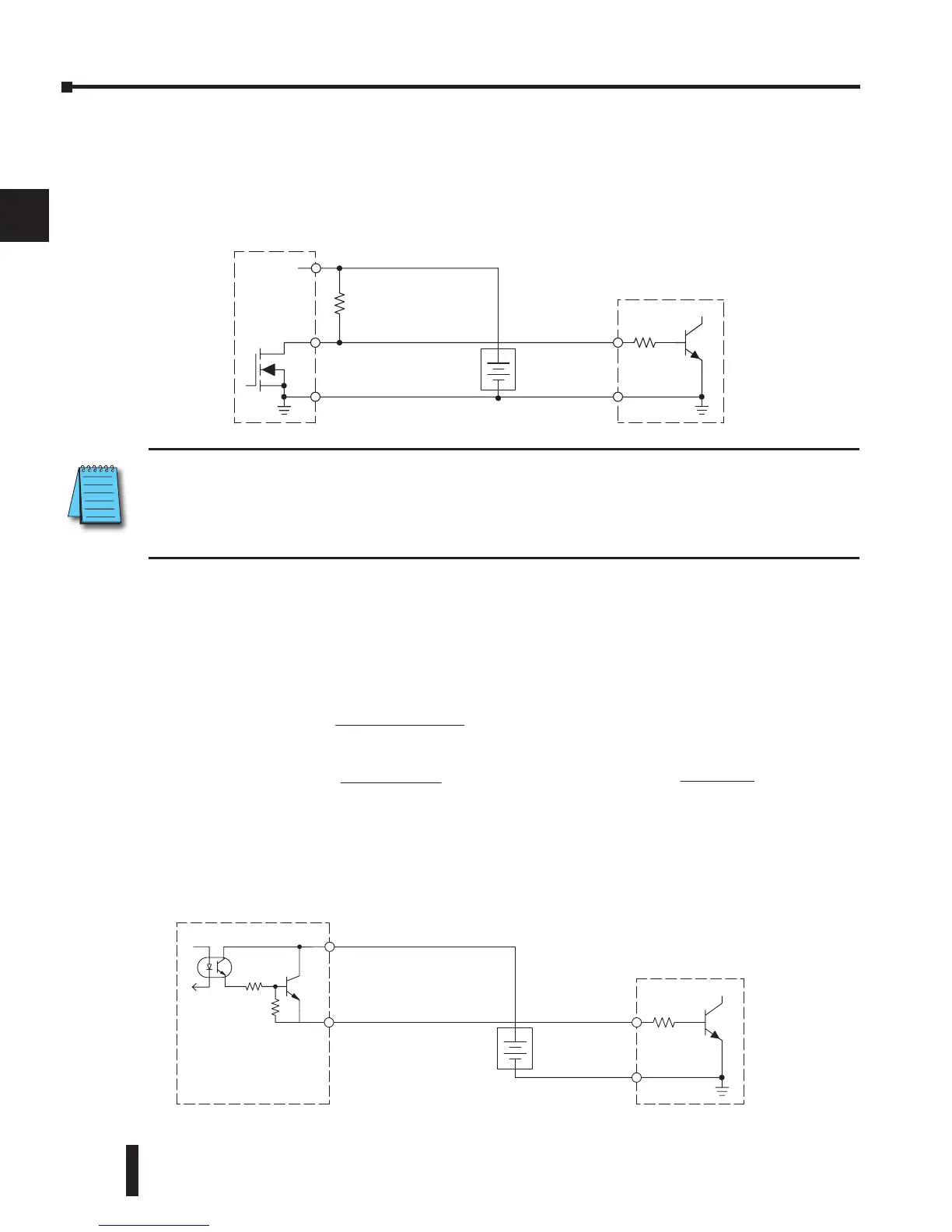
In the next example a PLC sinking DC output point is connected to the sinking input of a field
device. This is a little tricky, because both the PLC output and field device input are sinking
type. Since the circuit must have one sourcing and one sinking device, a sourcing capability
needs to be added to the PLC output by using a pull-up resistor. In the circuit below, a R
pull-up
is connected from the output to the DC output circuit power input.
NOTE 1: DO NOT attempt to drive a heavy load (>25mA) with this pull-up method
NOTE 2: Using the pull-up resistor to implement a sourcing output has the effect of inverting the output
point logic. In other words, the field device input is energized when the PLC output is OFF, from a ladder
logic point of view. Your ladder program must comprehend this and generate an inverted output. Or, you
may choose to cancel the effect of the inversion elsewhere, such as in the field device.
It is important to choose the correct value of R
pull-up
. In order to do so, you need to know the
nominal input current to the field device (I
input
) when the input is energized. If this value is
not known, it can be calculated as shown (a typical value is 15mA). Then use I
input
and the
voltage of the external supply to compute R
pull-up
. Then calculate the power P
pull-up
(in watts),
in order to size R
pull-up
properly.
Of course, the easiest way to drive a sinking input field device as shown below is to use a
DC sourcing output module. The Darlington NPN stage will have about 1.5 V ON-state
saturation, but this is not a problem with low-current solid-state loads.
Field Device
Output
Ground
Input
Common