DL205 User Manual, 4th Edition, Rev. D
4-47
Chapter 4: System Design and Configuration
1
2
3
4
5
6
7
8
9
10
11
12
13
14
A
B
C
D
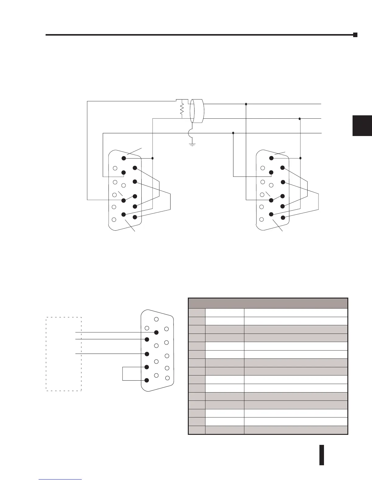
RS–485 Network (Modbus Only)
RS–485 signals are for longer distances (1000 meters maximum), and for multi-drop networks.
Use termination resistors at both ends of RS–485 network wiring, matching the impedance
rating of the cable (between 100 and 500 ohms).
RS–232 Network
Normally, the RS–232 signals are used for shorter distances (15 meters maximum), for
communications between two devices.
Port 2 Pin Descriptions (DL260 only)
1
5V 5 VDC
2
TXD2 Transmit Data (RS-232)
3
RXD2 Receive Data (RS-232)
4
RTS2 Ready to Send (RS–232)
5
CTS2 Clear to Send (RS–232)
6
RXD2– Receive Data – (RS–422/RS-485)
7
0V Logic Ground
8
0V Logic Ground
9
TXD2+ Transmit Data + (RS–422/RS–485)
10
TXD2 – Transmit Data – (RS–422/RS–485)
11
RTS2 + Request to Send + (RS–422/RS–485)
12
RTS2 – Request to Send – (RS–422/RS–485)
13
RXD2 + Receive Data + (RS–422/RS–485)
14
CTS2 + Clear to Send + (RS422/RS–485)
15
CTS2 – Clear to Send – (RS–422/RS–485)
DL260 CPU Port 2
TXD+ / RXD+
TXD– / RXD–