DL205 User Manual, 4th Edition, Rev. D
2-29
Chapter 2: Installation, Wiring and Specifications
1
2
3
4
5
6
7
8
9
10
11
12
13
14
A
B
C
D
I/O Wiring Checklist
Use the following guidelines when wiring the I/O modules in your system.
1. There is a limit to the size of wire the modules can accept. The table below lists the suggested AWG
for each module type. When making terminal connections, follow the suggested torque values.
*NOTE: 16 AWG Type TFFN or Type MTW is recommended. Other types of 16 AWG may be acceptable,
but it really depends on the thickness and stiffness of the wire insulation. If the insulation is too thick or
stiff and a majority of the module’s I/O points are used, then the plastic terminal cover may not close
properly or the connector may pull away from the module. This applies especially for high temperature
thermoplastics such as THHN.
2. Always use a continuous length of wire, do not combine wires to attain a needed length.
3. Use the shortest possible wire length.
4. Use wire trays for routing where possible.
5. Avoid running wires near high energy wiring. Also, avoid running input wiring close to output
wiring where possible.
6. To minimize voltage drops when wires must run a long distance, consider using multiple wires for
the return line.
7. Avoid running DC wiring in close proximity to AC wiring where possible.
8. Avoid creating sharp bends in the wires.
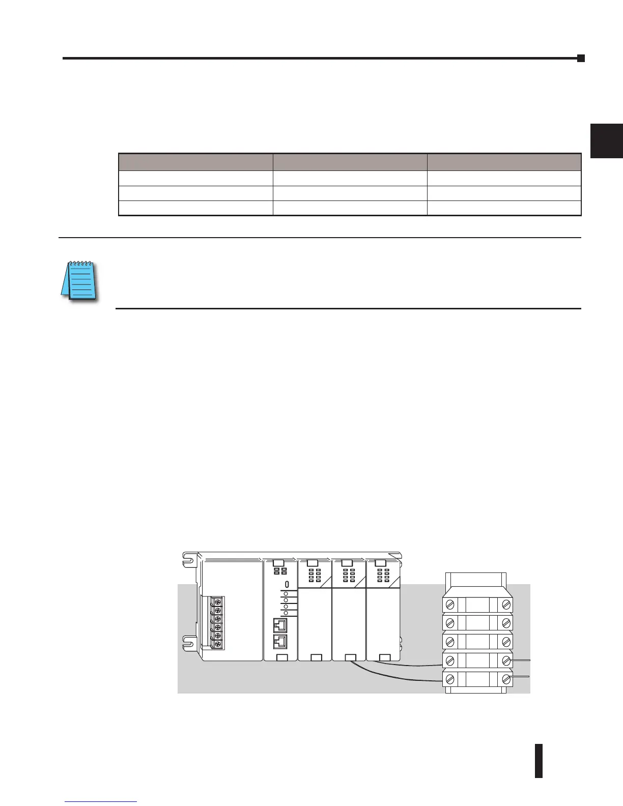
9. To reduce the risk of having a module with a blown fuse, we suggest you add external fuses to
your I/O wiring. A fast blow fuse, with a lower current rating than the I/O module fuse can
be added to each common, or a fuse with a rating of slightly less than the maximum current
per output point can be added to each output. Refer to our catalog for a complete line of
DINnectors, DIN-rail mounted fuse blocks.
Terminal type Suggested AWG Range Suggested Torque
10-Terminal Fixed 14 – 24 AWG 3.5 lb-inch (0.4 N·m)
10-Terminal Removable 16* – 24 AWG 7.81 lb-inch (0.88 N·m)
20-Terminal Removable 16* – 24 AWG 2.65 lb-in (0.3 N·m)