DL205 User Manual, 4th Edition, Rev. D
4-46
Chapter 4: System Design and Configuration
1
2
3
4
5
6
7
8
9
10
11
12
13
14
A
B
C
D
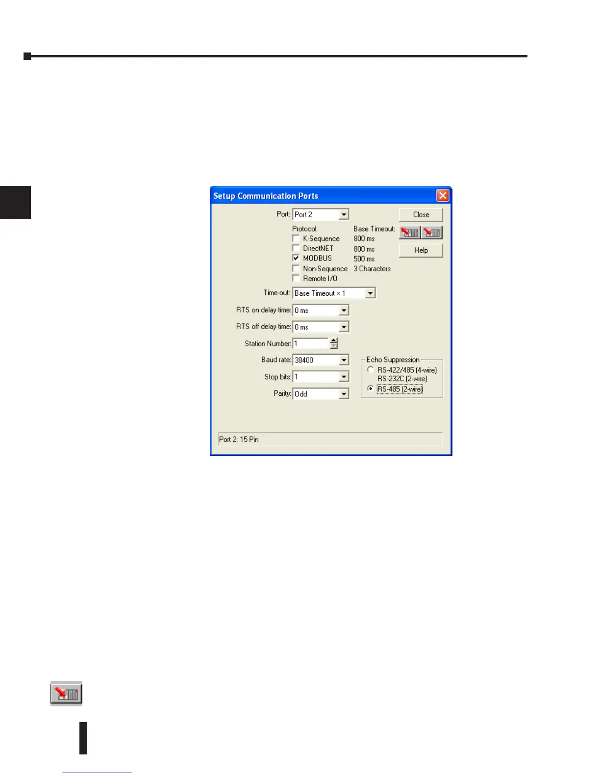
Modbus Port Configuration
In DirectSOFT, choose the PLC menu, then Setup, then “Secondary Comm Port.”
• Port: From the port number list box at the top, choose “Port 2.”
• Protocol: Click the check box to the left of “MODBUS” (use AUX 56 on the HPP, and select
“MBUS”), and then you’ll see the dialog box below.
• Timeout: Amount of time the port will wait after it sends a message to get a response before logging
an error.
• RTS On Delay Time: The amount of time between raising the RTS line and sending the data.
• RTS Off Delay Time: The amount of time between resetting the RTS line after sending the data.
• Station Number: For making the CPU port a Modbus master, choose “1.” The possible range for
Modbus slave numbers is from 1 to 247. Each slave must have a unique number. At powerup, the
port is automatically a slave, unless and until the DL06 executes ladder logic MWX/MRX network
instructions which use the port as a master. Thereafter, the port reverts back to slave mode until
ladder logic uses the port again.
• Baud Rate: The available baud rates include 300, 600, 900, 2400, 4800, 9600, 19200, and 38400
baud. Choose a higher baud rate initially, reverting to lower baud rates if you experience data errors
or noise problems on the network. Important: You must configure the baud rates of all devices on
the network to the same value. Refer to the appropriate product manual for details.
• Stop Bits: Choose 1 or 2 stop bits for use in the protocol.
• Parity: Choose none, even, or odd parity for error checking.
• Echo Suppression: Select the appropriate radio button based on the wiring configuration used on
port 2.
Then click the button indicated to send the Port configuration to the CPU, and click Close.