DL205 User Manual, 4th Edition, Rev. D
4-2
Chapter 4: System Design and Configuration
1
2
3
4
5
6
7
8
9
10
11
12
13
14
A
B
C
D
DL205 System Design Strategies
I/O System Configurations
The DL205 PLCs offer the following ways to add I/O to the system:
• Local I/O – consists of I/O modules located in the same base as the CPU.
• Local Expansion I/O – consists of I/O modules in expansion bases located close to the CPU local
base. Expansion cables connect the expansion bases and CPU base in daisy–chain format.
• Ethernet Remote Master – provides a low-cost, high-speed Ethernet Remote I/O link to Ethernet
Remote Slave I/O.
• Ethernet Base Controller – provides a low-cost, high-speed Ethernet link between a network master
to AutomationDirect Ethernet Remote Slave I/O.
• Remote I/O – consists of I/O modules located in bases which are serially connected to the local CPU
base through a Remote Master module, or may connect directly to the bottom port on a DL250–1
or DL260 CPU.
A DL205 system can be developed using many different arrangements of these configurations.
All I/O configurations use the standard complement of DL205 I/O modules and bases. Local
expansion requires using (–1) bases.
Networking Configurations
The DL205 PLCs offers the following way to add networking to the system:
• Ethernet Communications Module – connects DL205 systems (DL240, DL250–1 or DL260
CPUs only) and DL405 CPU systems in high–speed, peer–to–peer networks. Any PLC can initiate
communications with any other PLC when using either the ECOM or ECOM100 modules.
• Data Communications Module – connects a DL205 (DL240, DL250–1 and DL260 only) system
to devices using the DirectNET protocol, or connects as a slave to a Modbus RTU network.
• DL250–1 Communications Port – The DL250–1 CPU has a 15–Pin connector on Port 2 that
provides a built–in Modbus RTU or DirectNET master/slave connection.
• DL260 Communications Port – The DL260 CPU has a 15–Pin connector on Port 2 that provides
a built–in DirectNET master/slave or Modbus RTU master/slave connection with more Modbus
function codes than the DL250–1. (The DL260 MRX and MWX instructions allow you to
enter native Modbus addressing in your ladder program with no need to perform octal to decimal
conversions.) Port 2 can also be used for ASCII IN or ASCII OUT communications.
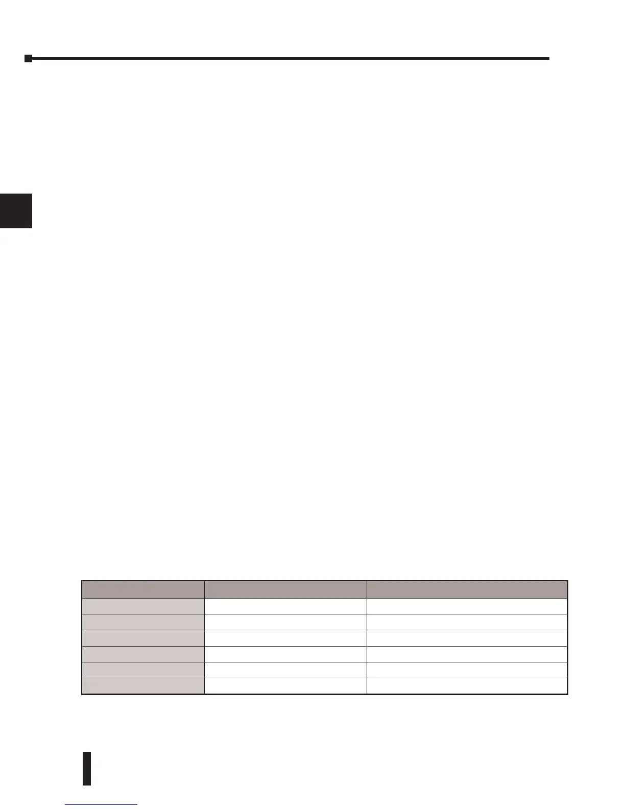
Module/Unit Master Slave
DL240 CPU
DirectNet, K–Sequence
DL250–1 CPU
DirectNet, Modbus RTU DirectNet, K–Sequence, Modbus RTU
DL260 CPU
DirectNet, Modbus RTU, ASCII DirectNet, K–Sequence, Modbus RTU, ASCII
ECOM
Ethernet Ethernet
ECOM100
Ethernet, Modbus TCP Ethernet, Modbus TCP
DCM
DirectNet DirectNet, K–Sequence, Modbus RTU