DL205 User Manual, 4th Edition, Rev. D
4-31
Chapter 4: System Design and Configuration
1
2
3
4
5
6
7
8
9
10
11
12
13
14
A
B
C
D
When configuring a Remote I/O channel for
fewer than 7 slaves, we must fill the remainder
of the table with zeros. This is necessary
because the CPU will try to interpret any non-
zero number as slave information.
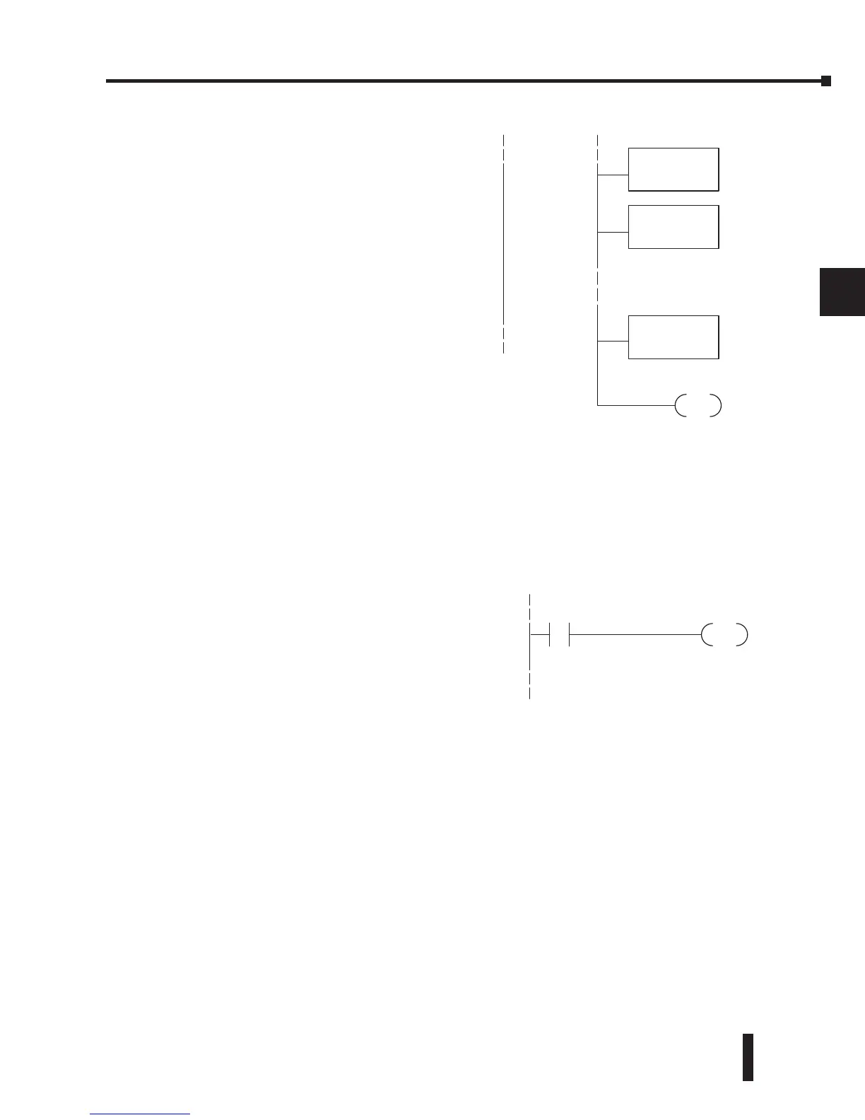
We continue our set-up program from the
previous page by adding a segment which
fills the remainder of the table with zeros.
The example to the right fills zeros for slave
numbers 2–7, which do not exist in our
example system.
On the last rung in the example program above, we set a special relay contact C740. This
particular contact indicates to the CPU the ladder program has finished specifying a remote
I/O system. At that moment, the CPU begins remote I/O communications. Be sure to include
this contact after any Remote I/O set-up program.
Remote I/O Test Program
Now we can verify the remote I/O link and
set-up program operation. A simple quick
check can be done with one rung of ladder,
shown to the right. It connects the first input
of the remote base with the first output. After
placing the PLC in RUN mode, we can go
to the remote base and activate its first input.
Then its first output should turn on.
X60
DirectSOFT
OUT
Y40
LD
K0
OUTD
V37710
OUTD
V37736