DL205 User Manual, 4th Edition, Rev. D
5-41
Chapter 5: Standard RLL Instructions
1
2
3
4
5
6
7
8
9
10
11
12
13
14
A
B
C
D
Timer, Counter and Shift Register Instructions
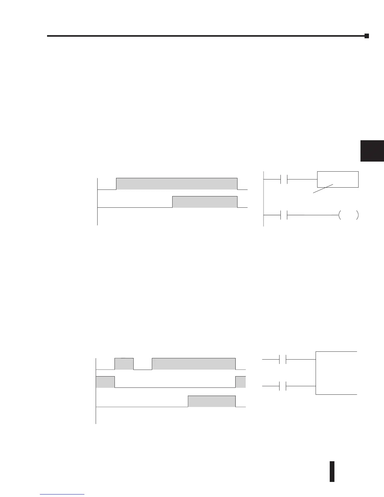
Using Timers
Timers are used to time an event for a desired length of time. The single input timer will time
as long as the input is on. When the input changes from on to off, the timer current value
is reset to 0. There is a tenth of a second and a hundredth of a second timer available with a
maximum time of 999.9 and 99.99 seconds respectively. A discrete bit is associated with each
timer to indicate that the current value is equal to or greater than the preset value. The timing
diagram below shows the relationship between the timer input, associated discrete bit, current
value, and timer preset.
Some applications that need an accumulating timer, meaning it has the ability to time, stop,
and then resume from where it previously stopped. The accumulating timer works similarly
to the regular timer, but two inputs are required. The enable input starts and stops the timer.
When the timer stops, the elapsed time is maintained. When the timer starts again, the timing
continues from the elapsed time. When the reset input is turned on, the elapsed time is cleared
and the timer will start at 0 when it is restarted. A tenth of a second and a hundredth of
a second timers are available with a maximum time of 9999999.9 and 999999.99 seconds
respectively. The timing diagram below shows the relationship between the timer input, timer
reset, associated discrete bit, current value, and timer preset.
X1
X1
T0
123456 78
0
01010203040500
Current
V
alue
TMRA T0
K30
X2
X2
Reset Input
Enable
Seconds
1/10
Seconds
TMR T1
K30
X1
X1
T1
123456 78
0
01020304050600