DL205 User Manual, 4th Edition, Rev. D
2-36
Chapter 2: Installation, Wiring and Specifications
1
2
3
4
5
6
7
8
9
10
11
12
13
14
A
B
C
D
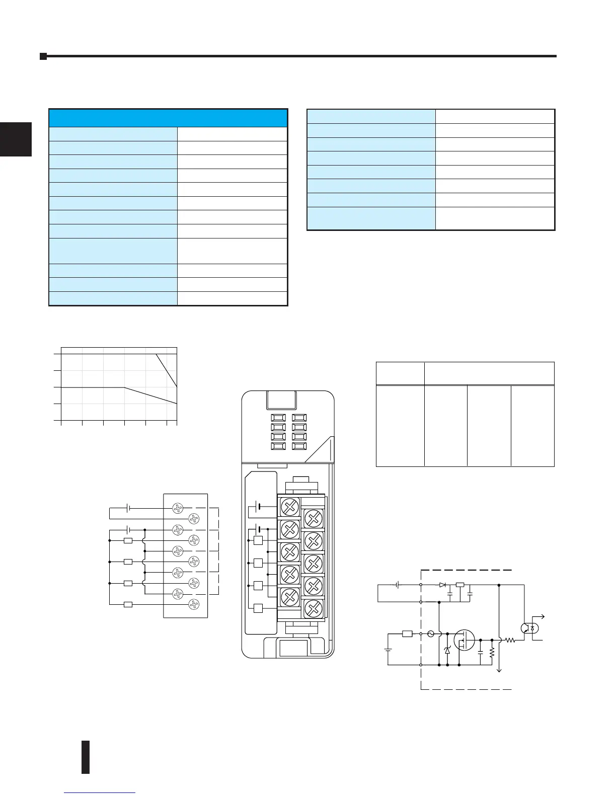
D2-04TD1, DC Output
D2-04TD1 DC Output
Outputs per Module
4 (current sinking)
Output Points Consumed
8 points (only first 4 pts. used)
Commons per Module
1 (4 I/O terminal points)
Output Type
NMOS FET (open drain)
Operating Voltage
10.2-26.4 VDC
Peak Voltage
40VDC
ON Voltage Drop
0.72 VDC maximum
AC Frequency
N/A
Max Load Current
(resistive)
4A/point
8A/common
Max Leakage Current
0.1 mA @ 40 VDC
Max Inrush Current
6A for 100 ms, 15A for 10 ms
Minimum Load Current
50 mA
External DC Required
24VDC @ 20 mA max.
Base Power Required 5VDC
60mA
OFF to ON Response
1ms
ON to OFF Response
1ms
Terminal Type (included)
Removable; D2-8IOCON
Status Indicator
Logic side
Weight
2.8 oz. (80 g)
Fuses
4 (1 per point)
(6.3 A slow blow, non-replaceable)
0
1
2
3
4
0
10 20 30 40 50 55
AmbientTemperature (˚C/˚F)
32 50 68 86 104 122131
C˚
F˚
6.3A
Derating Chart
At 40 mS duration, loads of 3.0A or greater cannot be used.
At 100 mS duration, loads of 2.0A or greater cannot be used.
Find the load current you expect to use and the duration that the
output is ON. The number at the intersection of the row and column
represents the switching cycles per minute. For example, a 1A
inductive load that is on for 100 ms can be switched on and off a
maximum of 60 times per minute. To convert this to duty cycle
percentage use: (duration x cycles)/60. In this example,
(60 x .1)/60 = .1, or 10% duty cycle.