DL205 User Manual, 4th Edition, Rev. D
3-46
Chapter 3: CPU Specifications and Operations
1
2
3
4
5
6
7
8
9
10
11
12
13
14
A
B
C
D
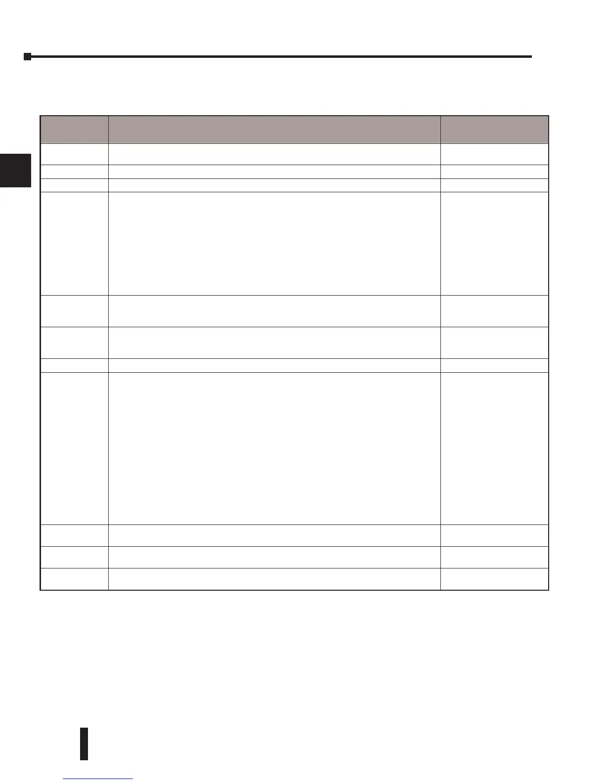
DL250–1 System V-memory (DL250 also)
System
V-memory
Description of Contents
Default Values/
Ranges
V3630–V3707
The default location for multiple preset values for UP/DWN and UP counter 1 or pulse
output function
N/A
V3710–V3767 The default location for multiple preset values for UP/DWN and UP counter 2. N/A
V3770–V3777 Not used N/A
V7620–V7627
V7620
V7621
V7622
V7623
V7624
V7625
V7626
V7627
Locations for DV–1000 operator interface parameters
Sets the V-memory location that contains the value
Sets the V-memory location that contains the message
Sets the total number (1 – 32) of V-memory locations to be displayed
Sets the V-memory location that contains the numbers to be displayed
Sets the V-memory location that contains the character code to be displayed
Sets the bit control pointer
Sets the power up mode
Change Preset Value password
V0 – V3760
V0 – V3760
1 – 32
V0 – V3760
V0 – V3760
V-memory for X, Y, or C
0,1,2,3,12
Default=0000
V7630
Starting location for the multi–step presets for channel 1. Since there are 24 presets
available, the default range is V3630 – V3707. You can change the starting point if
necessary.
Default: V3630
Range: V0 – V3710
V7631
Starting location for the multi–step presets for channel 2. Since there are 24 presets
available, the default range is V3710– V3767. You can change the starting point if
necessary.
Default: V3710
Range: V0 – V3710
V7632 Reserved
V7633 Sets the desired mode for the high-speed counter, interrupt, pulse catch, pulse train,
and input filter (see the D2-CTRINT manual, D2-CTRIF-M, for more information).
Location is also used for setting the with/without battery option, enable/disable CPU
mode change, and power-up in Run Mode option.
Default: 0060
Lower Byte Range:
Range: 0 – None
10 – Up
20 – Up/Dwn.
30 – Pulse Out
40 – Interrupt
50 – Pulse Catch
60 – Filtered Dis.
Upper Byte Range:
Bits 8 – 11, 14–15 Unused
Bit 12: With Batt. installed:
0 = disable BATT LED
1 = enable BATT LED
Bit 13: Power-up in Run
V7634
Contains set-up information for high-speed counter, interrupt, pulse catch,pulse train
output, and input filter for X0 (when D2–CTRINT is installed).
Default: 1006
V7635
Contains set-up information for high-speed counter, interrupt, pulse catch, pulse train
output, and input filter for X1 (when D2–CTRINT is installed).
Default: 1006
V7636
Contains set-up information for high-speed counter, interrupt, pulse catch, pulse train
output, and input filter for X2 (when D2–CTRINT is installed).
Default: 1006