DL205 User Manual, 4th Edition, Rev. D
2-48
Chapter 2: Installation, Wiring and Specifications
1
2
3
4
5
6
7
8
9
10
11
12
13
14
A
B
C
D
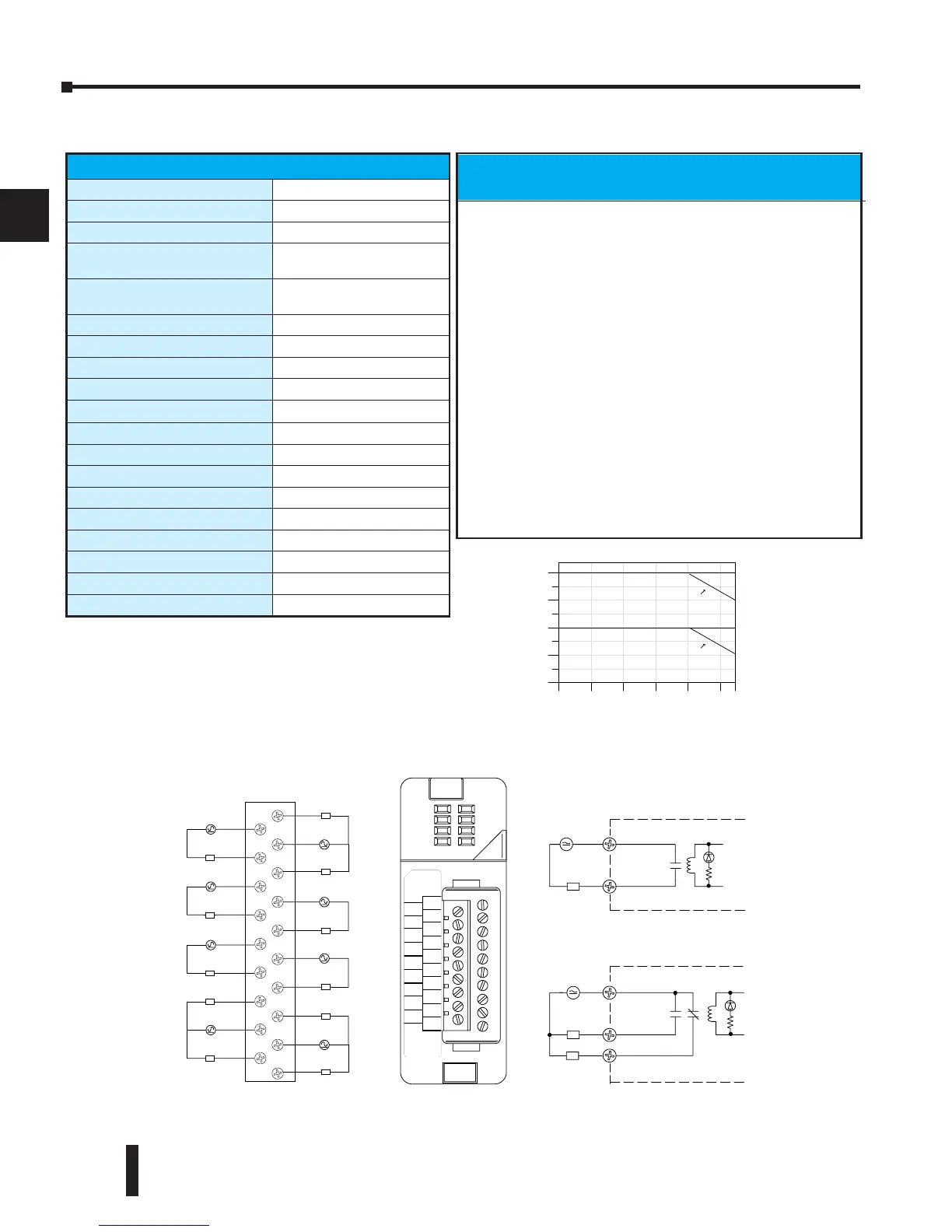
F2–08TRS, Relay Output
12-- 250VAC
7A 50/60Hz
OUTRELAY
F2-- 08TRS
0
1
2
3
4
5
NO 0
C0
NC 0
C3
NO 3
C5
NO 5
NC 7
C7
NO 6
C6
NC 6
NO 4
C4
NO 2
C2
NO 1
C1
NO7
12-- 28VDC
10ma--7A
6
7
L
Common
NO
Typical Circuit
L
Common
NO
NC
L
12-- 250VAC
12-- 28VDC
12-- 250VAC
12-- 28VDC
Internal Circuitry
Internal Circuitry
Typical Circuit
(Points0,6,&7 only)
(points1,2,3,4,5)
0
2
4
6
8
5A/pt.
0102030405055
AmbientTemperature (˚C/˚F)
32 50 68 86 104122 131
C˚
F˚
4A/
pt.
7A/pt.
6A/
pt.
Number
Points On
(100%duty
cycle)
C6
C7
NC 6
NC 7
NO 4
NO 5
C4
C5
NO 2
NO 3
C2
C3
NO 1
NC 0
C1
C0
NO 0
NO 6
NO 7
L
12-- 28VDC
12-- 250VAC
L
12-- 28VDC
12-- 250VAC
L
12-- 28VDC
12-- 250VAC
L
12-- 28VDC
12-- 250VAC
L
12-- 28VDC
12-- 250VAC
L
normally closed
L
12-- 28VDC
12-- 250VAC
L
normally closed
L
12-- 28VDC
12-- 250VAC
L
12-- 28VDC
12-- 250VAC
L
normally closed
Derating Chart
F2-08TRS Relay Output
Outputs per Module
8
Outputs Points Consumed
8
Commons per Module
8 (isolated)
Output Type
3, Form C (SPDT)
5, Form A (SPST normally open)
Operating Voltage
7A @ 12–28 VDC, 12–250 VAC
0.5A @ 120VDC
Peak Voltage
150VDC, 265VAC
ON Voltage Drop
N/A
AC Frequency
47 to 63Hz
Minimum Load Current
10mA @ 12VDC
Max Load Current (resistive)
7A/point
3
(subject to derating)
Max Leakage Current
N/A
Max Inrush Current
12A
Base Power Required 5VDC
670mA
OFF to ON Response
15ms (typical)
ON to OFF Response
5ms (typical)
Terminal Type (included)
Removable; D2-16IOCON
Status Indicator
Logic side
Weight
5.5 oz. (156g)
Fuses
None
Typical Relay Life
1
(Operations) at Room
Temperature
Voltage & Load Current
Type of Load
2
50mA 5A 7A
24VDC Resistive 10M 600k 300k
24VDC Solenoid - 150k 75k
110VDC Resistive – 600k 300k
110VDC Solenoid – 500k 200k
220VAC Resistive – 300k 150k
220VAC Solenoid – 250k 100k
1) Contact life may be extended beyond those values shown with
the use of arc suppression techniques described in the DL205 User
Manual. Since these modules have no leakage current, they do not
have built-in snubber. For example, if you place a diode across a
24VDC inductive load, you can significantly increase the life of the
relay.
2) At 120VDC 0.5 A resistive load, contact life cycle is 200k cycles.
3) Normally, closed contacts have 1/2 the current handling
capability of the normally open contacts.