DL205 User Manual, 4th Edition, Rev. D
2-39
Chapter 2: Installation, Wiring and Specifications
1
2
3
4
5
6
7
8
9
10
11
12
13
14
A
B
C
D
F2–16TD1(2)P, DC Output With Fault Protection
When these modules are installed, 16
X bits are automatically assigned as
the fault status indicator. Each X bit
indicates the fault status of each output.
Fault Status X bit Fault Status Indication
Missing external 24VDC All 16 X bits are on.
Open load
1
Only the X bit assigned to the
faulted output is on
Over temperature
Over load current
Fault Status Operation
Missing external 24VDC Apply external 24VDC
Open load
1
Connect the load.
Over temperature
Turn the output (Y bit) off or
power cycle the PLC
Over load current
The fault status indicators (X bits) can be reset
by performing the indicated operations in the
following table:
NOTE 1: Open load detection can be disabled by
removing the jumper switch J6 on the module PC
board.
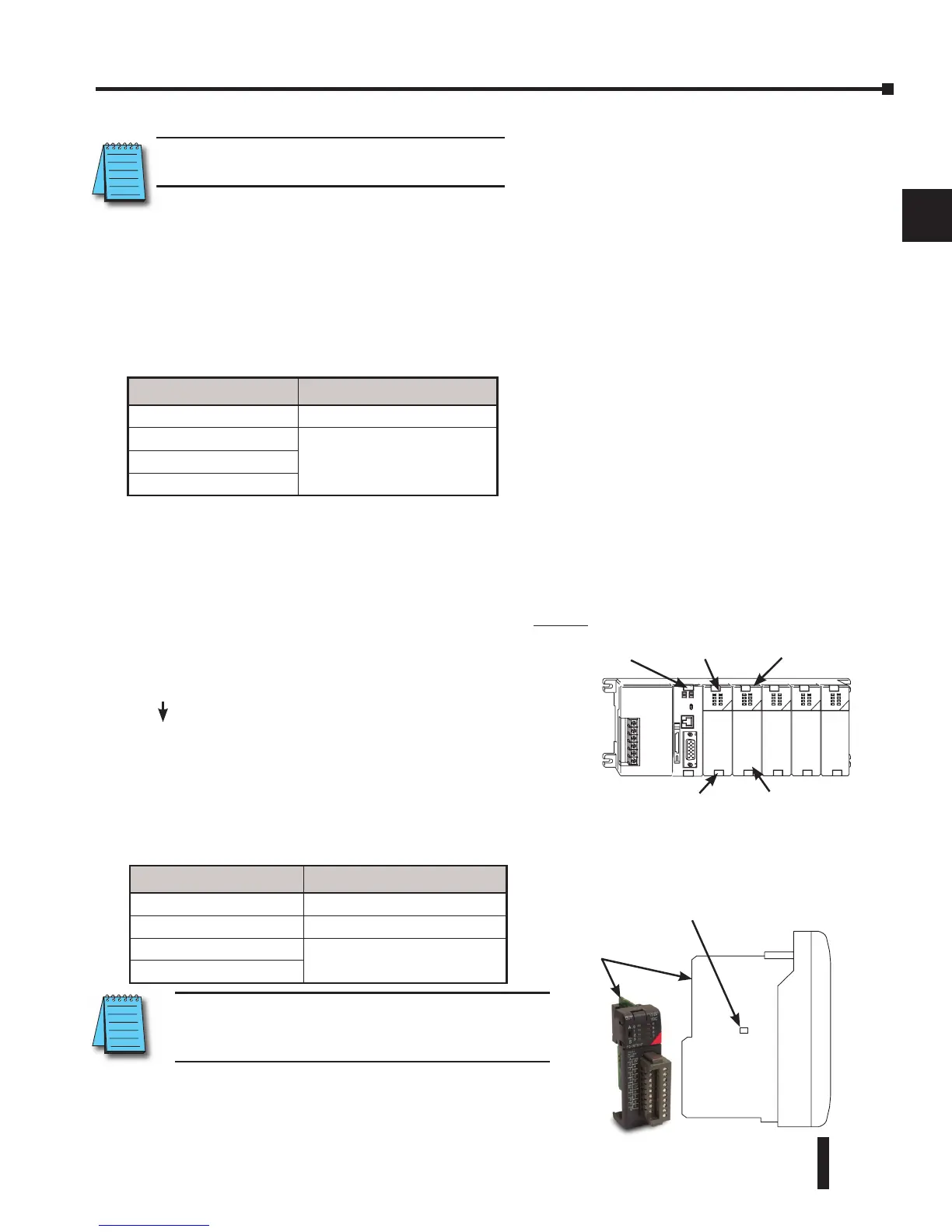
Example
In this example, X10-X27 are assigned as the fault
status indicator.
X10: Fault status indicator for Y0
X11: Fault status indicator for Y1
X26: Fault status indicator for Y16
X27: Fault status indicator for Y17
These modules detect the following fault status and
turn the related X bit(s) on.
1. Missing external 24VDC for the module
2. Open load
1
3. Over temperature (the output is shut down)
4. Over load current (the output is shut down)
NOTE: Not supported in D2-230, D2-240
and D2-250 CPUs.