DL205 User Manual, 4th Edition, Rev. D
4-13
Chapter 4: System Design and Configuration
1
2
3
4
5
6
7
8
9
10
11
12
13
14
A
B
C
D
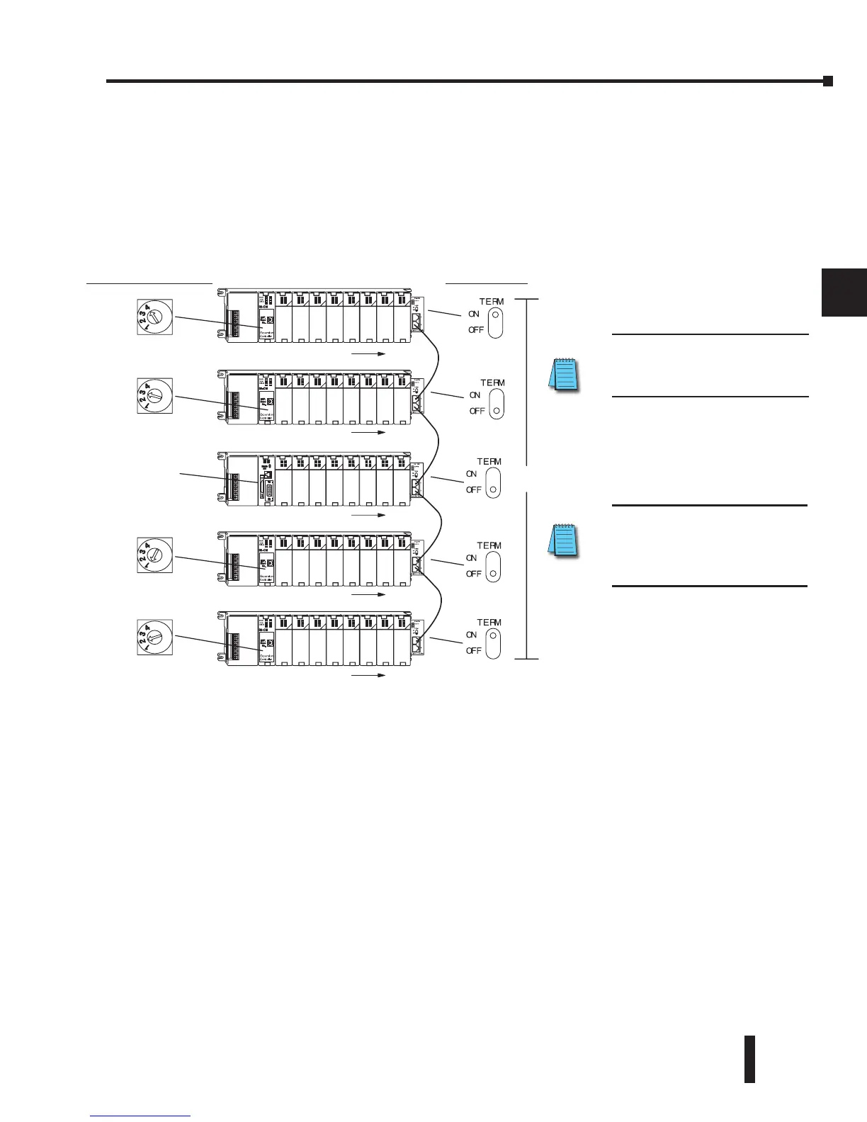
DL260 Local Expansion System
The D2–260 supports local expansion up to five total bases (one CPU base + four local
expansion bases) and up to a maximum of 1280 total I/O points. An example local expansion
system is shown below. All local and expansion I/O points are updated on every CPU scan.
No specialty modules can be located in the expansion bases (refer to the Module Placement
Table earlier in this chapter for restrictions).
• The CPU base can be located at any base position in the expansion system.
• All discrete and analog modules are supported in the expansion bases. Specialty modules are
not supported in the expansion bases.
• The D2–CMs do not have to be in successive numerical order; however, the numerical rotary
selection determines the X and Y addressing order. The CPU will recognize the local and
expansion I/O on power–up. Do not duplicate numerical selections.
• The TERM (termination) switch on the two endmost D2–EMs must be in the ON position.
The other D2–EMs in between should be in the OFF position.
• Use the D2–EXCBL–1 or equivalent cable to connect the D2–EMs together. Either of the
RJ45 ports (labeled A and B) on the D2–EM can be used to connect one base to another.
D2–EM Termination
Switch Settings
Base Number Selection
D2–260
CPU
I/O addressing #1
I/O addressing #2
I/O addressing #3
I/O addressing #4
I/O addressing #5
30m (98ft.) max. cable length
NOTE: Do not use Ethernet hubs
to connect the local expansion
system together.
NOTE: Use D2-EXCBL-1 (1m)
(Category 5 straight-through
cable) to connect the D2-EMs
together.
 Loading...

