DL205 User Manual, 4th Edition, Rev. D
3-21
Chapter 3: CPU Specifications and Operations
1
2
3
4
5
6
7
8
9
10
11
12
13
14
A
B
C
D
CPU Operation
Achieving the proper control for your equipment or process requires a good understanding
of how DL205 CPUs control all aspects of system operation. The flowchart below shows the
main tasks of the CPU operating system. In this section, we
will investigate four aspects of CPU operation:
• CPU Operating System — The CPU manages all aspects of
system control.
• CPU Operating Modes — The three primary modes of
operation are Program Mode, Run Mode, and Test Mode.
• CPU Timing — The two important areas we discuss are the
I/O response time and the CPU scan time.
• CPU Memory Map — The CPU’s memory map shows the
CPU addresses of various system resources, such as timers,
counters, inputs, and outputs.
CPU Operating System
At power up, the CPU initializes the internal electronic
hardware. Memory initialization starts with examining
the retentive memory settings. In general, the contents of
retentive memory are preserved, and non-retentive memory
is initialized to zero (unless otherwise specified).
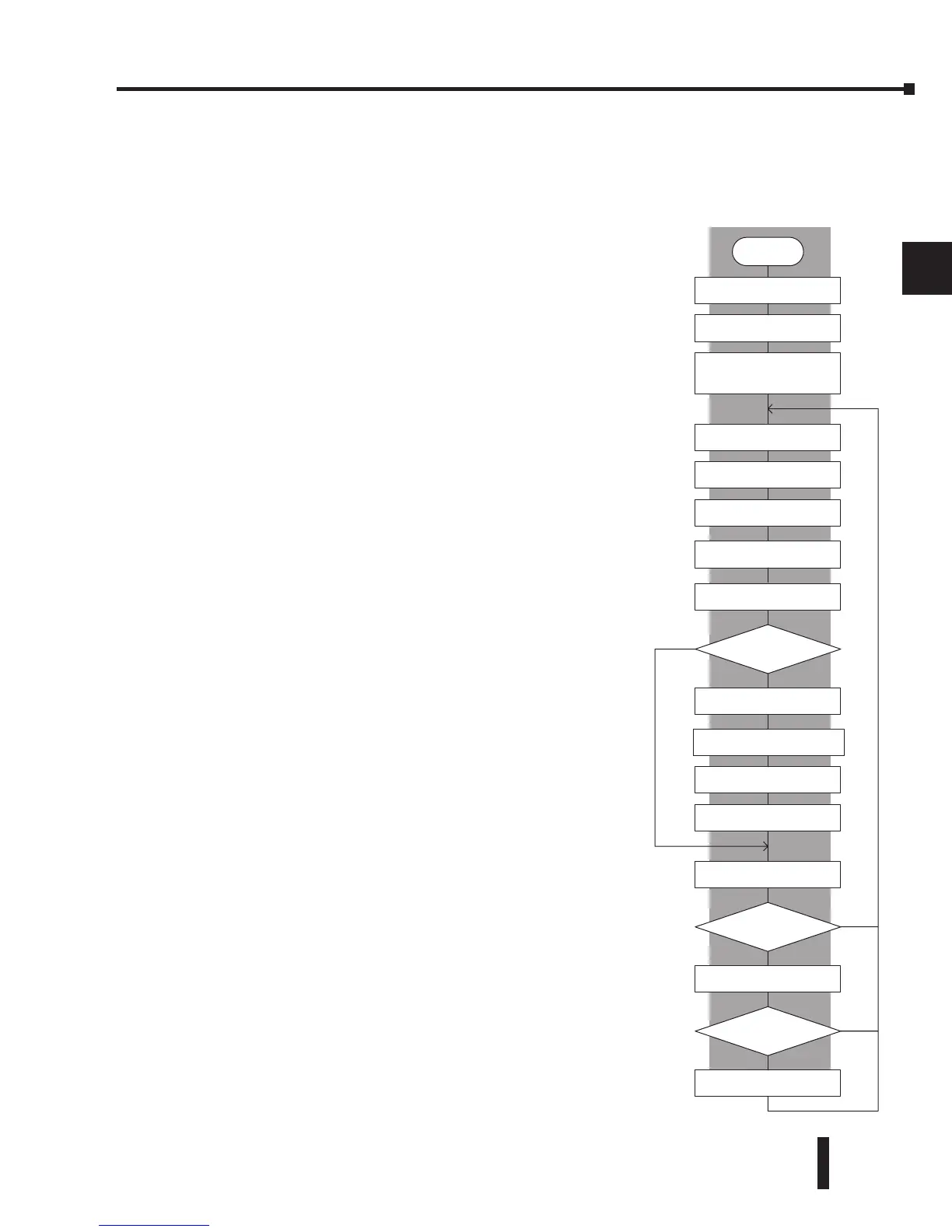
After the one-time power-up tasks, the CPU begins the
cyclical scan activity. The flowchart to the right shows how
the tasks differ based on the CPU mode and the existence
of any errors. The “scan time” is defined as the average
time around the task loop. Note that the CPU is always
reading the inputs, even during program mode. This allows
programming tools to monitor input status at any time.
The outputs are only updated in Run mode. In Program
mode, they are in the off state.
In Run Mode, the CPU executes the user ladder program.
Immediately afterwards, any PID loops which are
configured are executed (DL250-1 and DL260). Then
the CPU writes the output results of these two tasks to the
appropriate output points.
Error detection has two levels: Non-fatal and fatal. Non-
fatal errors are reported, but the CPU remains in its current
mode. If a fatal error occurs, the CPU is forced into
program mode and the outputs go off.
YES
Power up
Initialize hardware
Check I/O module
config. and verify
Initialize various memory
based on retentive
configuration
Update input
Read input data from
Specialty and Remote I/O
Service peripheral
PGM
Mode?
RUN
Execute ladder program
Update output
Write output data to
Specialty and Remote I/O
Do diagnostics
OK
NO
NO
Fatal error
Force CPU into
PGM mode
OK?
Report the error, set flag,
register, turn on LED
YES
CPU Bus Communication
Update Clock / Calendar
PID Operations (DL250-1/DL260)