DL205 User Manual, 4th Edition, Rev. D
3-38
Chapter 3: CPU Specifications and Operations
1
2
3
4
5
6
7
8
9
10
11
12
13
14
A
B
C
D
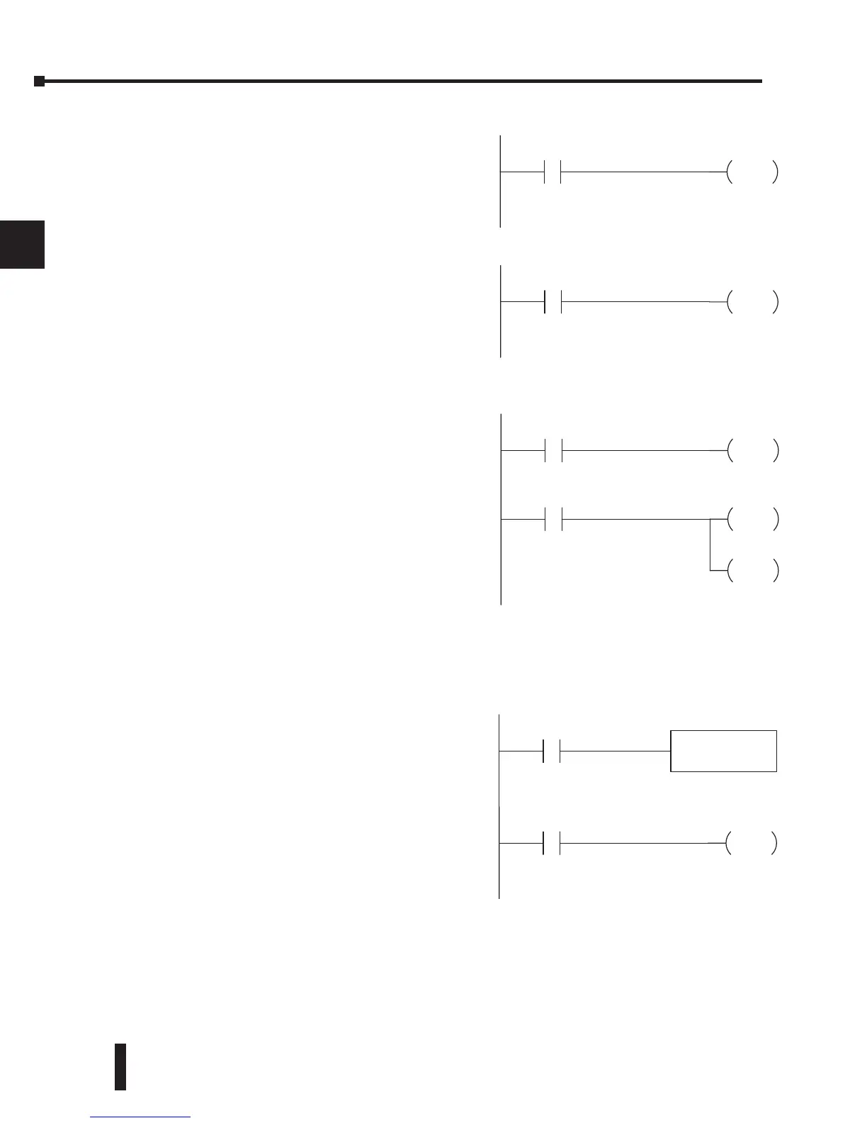
Input Points (X Data Type)
The discrete input points are noted by an X
data type. Up to 512 discrete input points
are available with the DL205 CPUs. In this
example, the output point Y0 will be turned on
when input X0 energizes.
Output Points (Y Data Type)
The discrete output points are noted by a Y
data type. Up to 512 discrete output points
are available with the DL205 CPUs. In this
example, output point Y1 will turn on when
input X1 energizes.
Control Relays (C Data Type)
Control relays are discrete bits normally used to
control the user program. The control relays do
not represent a real world device; that is, they
cannot be physically tied to switches, output
coils, etc. Control relays are internal to the
CPU and can be programmed as discrete inputs
or discrete outputs. These locations are used in
programming the discrete memory locations (C)
or the corresponding word location which has 16
consecutive discrete locations. In this example,
memory location C5 will energize when input
X10 turns on. The second rung shows a simple
example of how to use a control relay as an input.
Timers and Timer Status Bits (T Data Type)
The number of timers available depends on the
model of CPU you are using. The tables at
the end of this section provide the number of
timers for the DL230, DL240, D2-250-1 and
DL260. Regardless of the number of timers,
you have access to timer status bits that reflect
the relationship between the current value and
the preset value of a specified timer. The timer
status bit will be on when the current value is
equal to or greater than the preset value of a
corresponding timer.
When input X0 turns on, timer T1 will start.
When the timer reaches the preset of 3 seconds
(K of 30), timer status contact T1 turns on.
When T1 turns on, output Y12 turns on.
Y0
OUT
X0
Y1
OUT
X1
Y12
OUT
T1
TMR T1
K30
X0
C5
OUT
X10
Y10
OUT
C5
Y20
OUT