DL205 User Manual, 4th Edition, Rev. D
2-22
Chapter 2: Installation, Wiring and Specifications
1
2
3
4
5
6
7
8
9
10
11
12
13
14
A
B
C
D
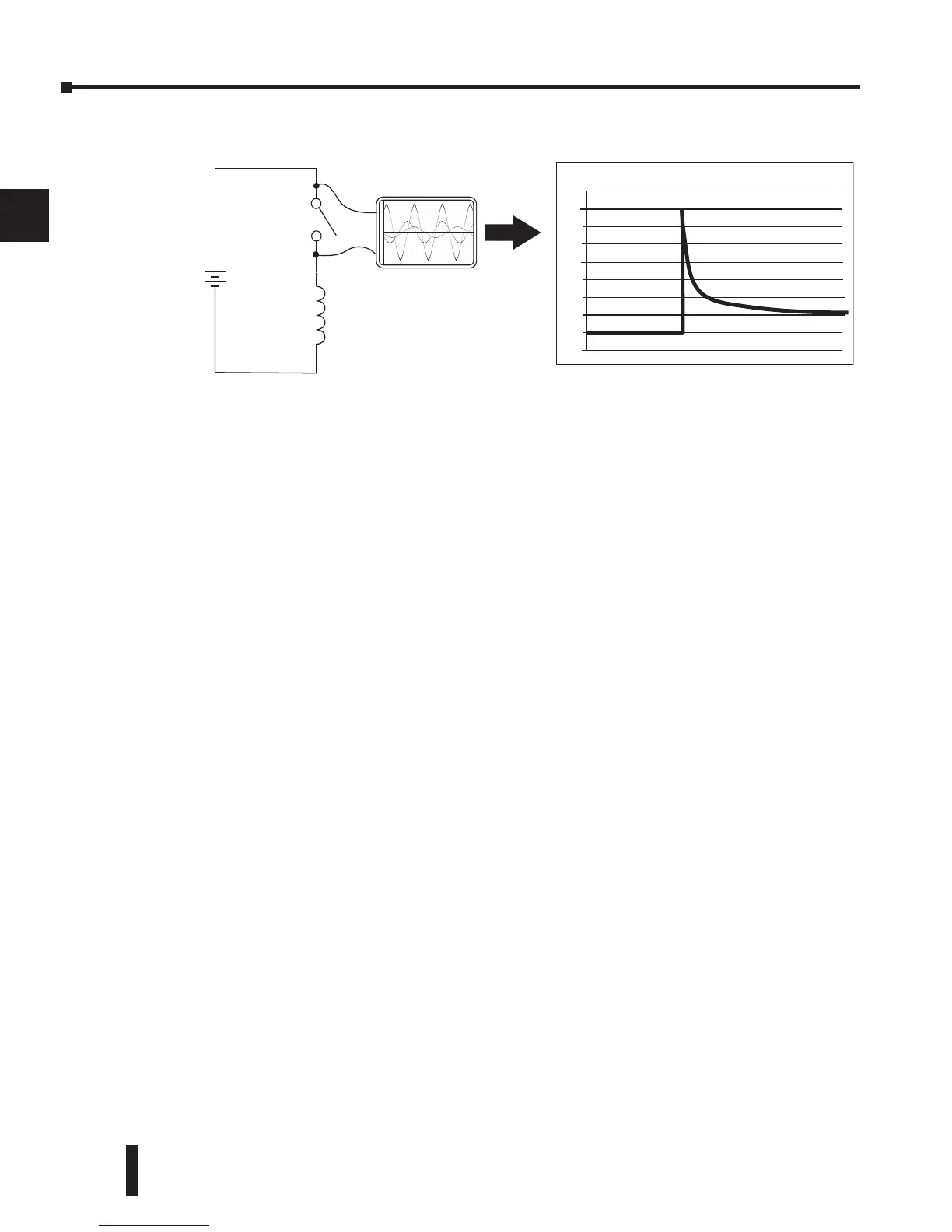
In the same circuit, replacing the relay with a larger 24V/290mA/7W relay will generate a
transient voltage exceeding 800V (not shown). Transient voltages like this can cause many
problems, including:
• Relay contacts driving the coil may experience arcing, which can pit the contacts and reduce the
relay’s lifespan.
• Solid state (transistor) outputs driving the coil can be damaged if the transient voltage exceeds the
transistor’s ratings. In extreme cases, complete failure of the output can occur the very first time a
coil is de-energized.
• Input circuits, which might be connected to monitor the coil or the output driver, can also be
damaged by the transient voltage.
A very destructive side-effect of the arcing across relay contacts is the electromagnetic
interference (EMI) it can cause. This occurs because the arcing causes a current surge, which
releases RF energy. The entire length of wire between the relay contacts, the coil, and the
power source carries the current surge and becomes an antenna that radiates the RF energy. It
will readily couple into parallel wiring and may disrupt the PLC and other electronics in the
area. This EMI can make an otherwise stable control system behave unpredictably at times.
PLC’s Integrated Transient Suppressors
Although the PLC’s outputs typically have integrated suppressors to protect against transients,
they are not capable of handling them all. It is usually necessary to have some additional
transient suppression for an inductive load.
The next example uses the same 24V/125mA/3W relay used earlier. This example measures
the PNP transistor output of a D0-06DD2 PLC, which incorporates an integrated Zener diode
for transient suppression. Instead of the 140V peak in the first example, the transient voltage
here is limited to about 40V by the Zener diode. While the PLC will probably tolerate repeated
transients in this range for some time, the 40V is still beyond the module’s peak output voltage
rating of 30V.