DL205 User Manual, 4th Edition, Rev. D
5-56
Chapter 5: Standard RLL Instructions
1
2
3
4
5
6
7
8
9
10
11
12
13
14
A
B
C
D
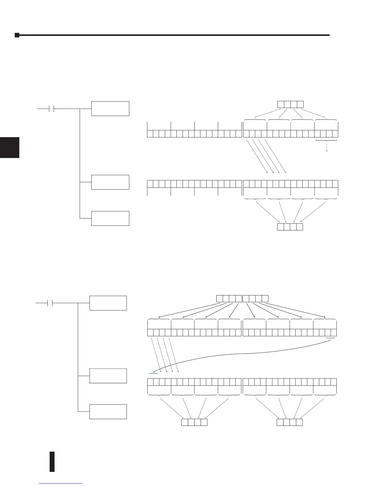
Changing the Accumulator Data
Instructions that manipulate data also use the accumulator. The result of the manipulated
data resides in the accumulator. The data that was being manipulated is cleared from the
accumulator. The following example loads the constant value 4935 into the accumulator,
shifts the data right 4 bits, and outputs the result to V1410.
Some of the data manipulation instructions use 32 bits. They use two consecutive V-memory
locations or an 8-digit BCD constant to manipulate data in the accumulator.
The following example rotates the value 67053101 two bits to the right and outputs the value
to V1410 and V1411.
LD
K4935
X1
Load the value 4935 into the
accumulator
Shift the data in the accumulator
4 bits (K4) to the right
Output the lower 16 bits of the
accumulator to V1410
31 30 29 28 27 26 25 24 23 22 21 20 19 18 17 16
Shifted out of
accumulator
049 3
493 5
SHFR
K4
OUT
V1410
0000000000000000
31 30 29 28 27 26 25 24 23 22 21 20 19 18 17 16
0000000000000000
The upper 16 bits of the accumulator
will be set to 0
15 14 13 12 11 10 987654
31 30 29 28 27 26 25 24 23 22 21 20 19 18 17 1631 30 29 28 27 26 25 24 23 22 21 20 19 18 17 16
Acc.
Acc.
LDD
K67053101
X1
Load the value 67053101
into the accumulator
Rotate the data in the
accumulator 2 bits to the right
Output the value in the
accumulator to V1410 and V1411
0011000100000001
V1410
01001100010000000000010000000000
15 14 13 12 11 10 987654321031 30 29 28 27 26 25 24 23 22 21 20 19 18 17 16
8C4 0
ROTR
K2
OUTD
V1410
0101100111000001
31 30 29 28 27 26 25 24 23 22 21 20 19 18 17 16
0110011100000101
15 14 13 12 11 10 9876543210
31 30 29 28 27 26 25 24 23 22 21 20 19 18 17 1631 30 29 28 27 26 25 24 23 22 21 20 19 18 17
16
Acc.
Acc.
V141
1
59C 1
Constant
670 5 310 1