DL205 User Manual, 4th Edition, Rev. D
5-73
Chapter 5: Standard RLL Instructions
1
2
3
4
5
6
7
8
9
10
11
12
13
14
A
B
C
D
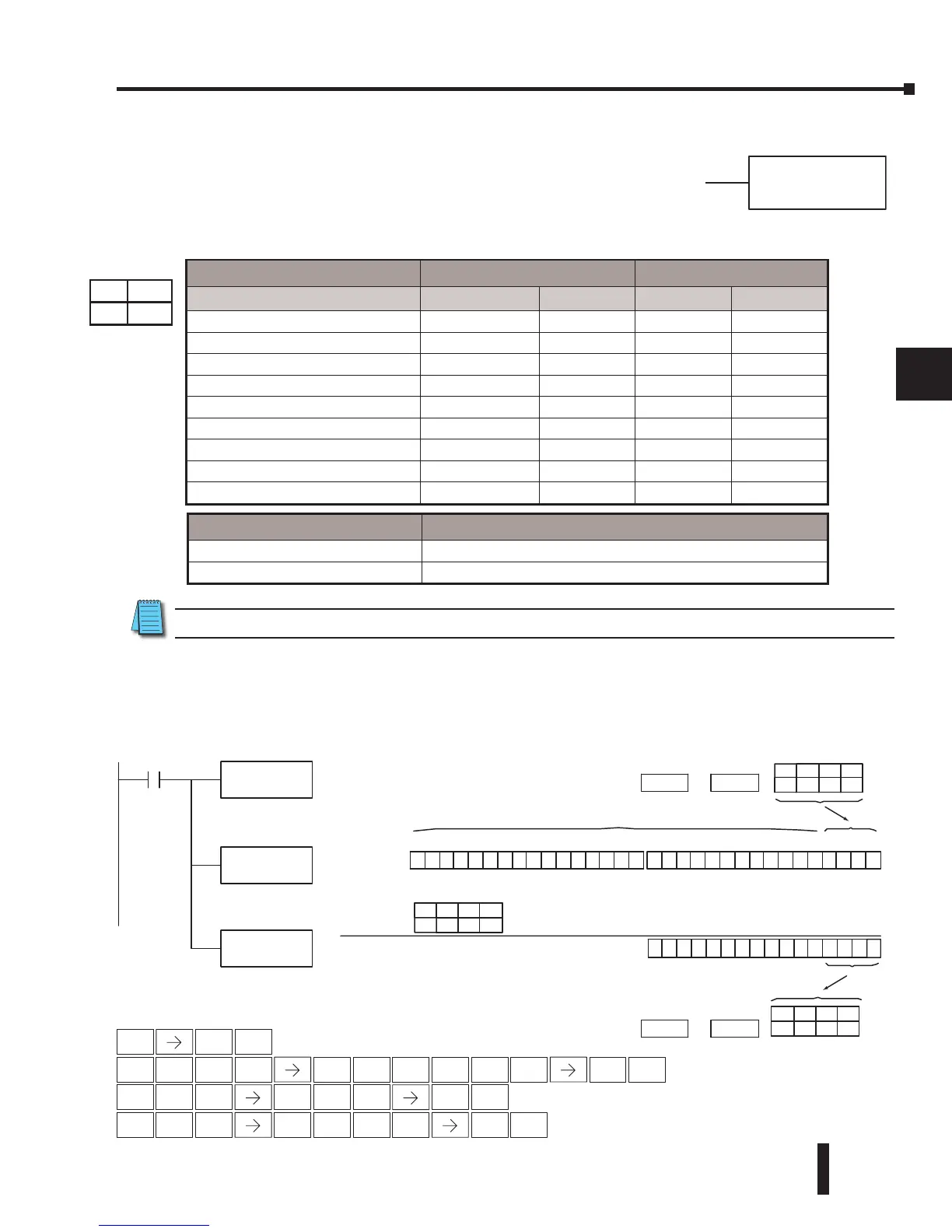
And Formatted (ANDF)
The And Formatted instruction logically ANDs the binary value in
the accumulator and a specified range of discrete memory bits (1 to
32). The instruction requires a starting location (Aaaa) and number
of bits (Kbbb) to be ANDed. Discrete status flags indicate if the result
is zero or a negative number (the most significant bit =1).
NOTE: Status flags are valid only until another instruction uses the same flag.
In the following example, when X1 is on, the Load Formatted instruction loads C10–C13
(4 binary bits) into the accumulator. The accumulator content is logically ANDed with the bit
pattern from Y20–Y23 using the And Formatted instruction. The Out Formatted instruction
outputs the accumulator’s lower four bits to C20–C23.
Discrete Bit Flags Description
SP63 Will be on if the result in the accumulator is zero
SP70 Will be on if the result in the accumulator is negative
bbbK
ANDF A aaa
Load the status of 4
consecutive bits (C10-C13)
into the accumulator
ANDF
Y20
K4
And the binary bit pattern
(Y20-Y23) with the value in
the accumulator
OUTF
C20
Copy the value in the lower
4 bits in accumulator to
C20-C23
AND (Y20-Y23)
The unused accumulator bits are set to zero
Location Constant
ConstantLocation
ON
ON ON
OFF
ON OFFOFFOFF
ON
OFFOFFOFF
C20
K4
LDF
Handheld Programmer Keystrokes
1
B
ENT
1
B
4
E
0
A
0
A
ENT
STR
$
SHFT
ANDST
L
3
D
E
ENT
Operand Data Type DL250-1 Range DL260 Range
A aaa bbb aaa bbb
Inputs X 0–777 – 0–1777 –
Outputs Y 0–777 – 0–1777 –
Control Relays C 0–1777 – 0–3777 –
Stage bits S 0–1777 – 0–1777 –
Timer bits T 0–377 – 0–377 –
Counter bits CT 0–177 – 0–377 –
Special Relays SP 0-777 – 0–777 –
Global I/O GX/GY - – 0-3777 –
Constant K - 1–32 - 1–32
230
240
250-1
260
DS Used
HPP Used