DL205 User Manual, 4th Edition, Rev. D
5-164
Chapter 5: Standard RLL Instructions
1
2
3
4
5
6
7
8
9
10
11
12
13
14
A
B
C
D
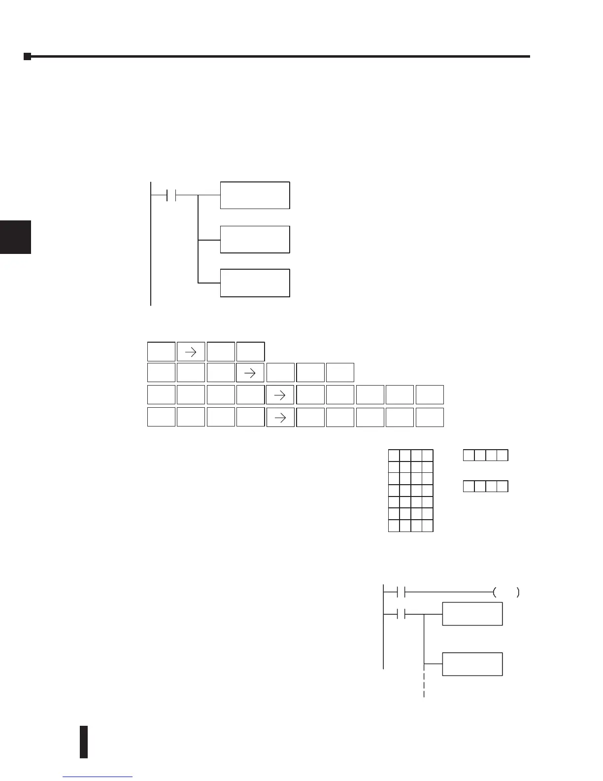
In the following example, when X1 is on, the constant value (K6) is loaded into the accumulator
using the Load instruction. This value specifies the length of the table and is placed in the first
stack location after the Load Address instruction is executed. The octal address 1400 (V1400)
is the starting location for the source table and is loaded into the accumulator. The destination
location (V1500) is specified in the Remove from Table instruction. The table counter will be
decreased by “1” after the instruction is executed.
Since the table counter specifies the range of data
that will be removed from the table, it is important
to understand how the table locations are numbered.
If you examine the example table, you’ll notice that
the data locations are numbered from the top of the
table. For example, if the table counter started at 6,
then all 6 of the locations would be affected during
the instruction execution.
Also, our example uses a normal input contact (X1) to
control the execution. Since the CPU scan is extremely
fast, and the pointer decrements automatically, the
data would be removed from the table very quickly.
If this is a problem for your application, you have the
option of using a one-shot (PD) to remove one value
each time the input contact transitions from low to
high.
 Loading...

