DL205 User Manual, 4th Edition, Rev. D
5-167
Chapter 5: Standard RLL Instructions
1
2
3
4
5
6
7
8
9
10
11
12
13
14
A
B
C
D
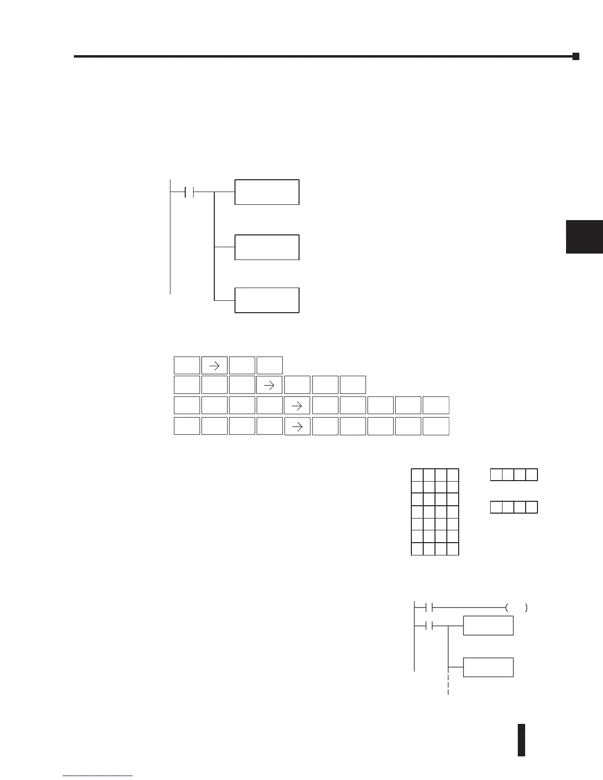
In the following example, when X1 is on, the constant value (K6) is loaded into the accumulator
using the Load instruction. This value specifies the length of the table and is placed in the first
stack location after the Load Address instruction is executed. The octal address 1400 (V1400),
which is the starting location for the destination table and table counter, is loaded into the
accumulator. The source location (V1500) is specified in the Add to Top instruction. The
table counter will be increased by “1” after the instruction is executed.
For the ATT instruction, the table counter determines
the number of additions that can be made before the
instruction will stop executing. So, it is helpful to
understand how the system uses this counter to control
the execution.
For example, if the table counter was set to 2, and the
table length was 6 words, then there could only be 4
additions of data before the execution was stopped. This
can be calculated easily by:
Table length – table counter = number of executions
Also, our example uses a normal input contact (X1) to
control the execution. Since the CPU scan is extremely
fast, and the table counter increments automatically, the
data would be moved into the table very quickly. If this
is a problem for your applicaton, you have an option of
using a one-shot (PD) to add one value each time the
input contact transitions from low to high.
 Loading...

