DL205 User Manual, 4th Edition, Rev. D
5-204
Chapter 5: Standard RLL Instructions
1
2
3
4
5
6
7
8
9
10
11
12
13
14
A
B
C
D
Bit element – used for printing the state of the designated bit in V-memory or a relay bit.
The bit element can be assigned by the designating point (.) and bit number preceded by the
V-memory number or relay number. The output type is described as shown in the table below.
Example:
V2000.15 Prints the status of bit 15 in V2000, in 1/0 format
C100 Prints the status of C100 in 1/0 format
C100 : BOOL Prints the status of C100 in TRUE/FALSE format
C100 : ON/OFF Prints the status of C100 in ON/OFF format
V2000.15 : BOOL Prints the status of bit 15 in V2000 in TRUE/FALSE format
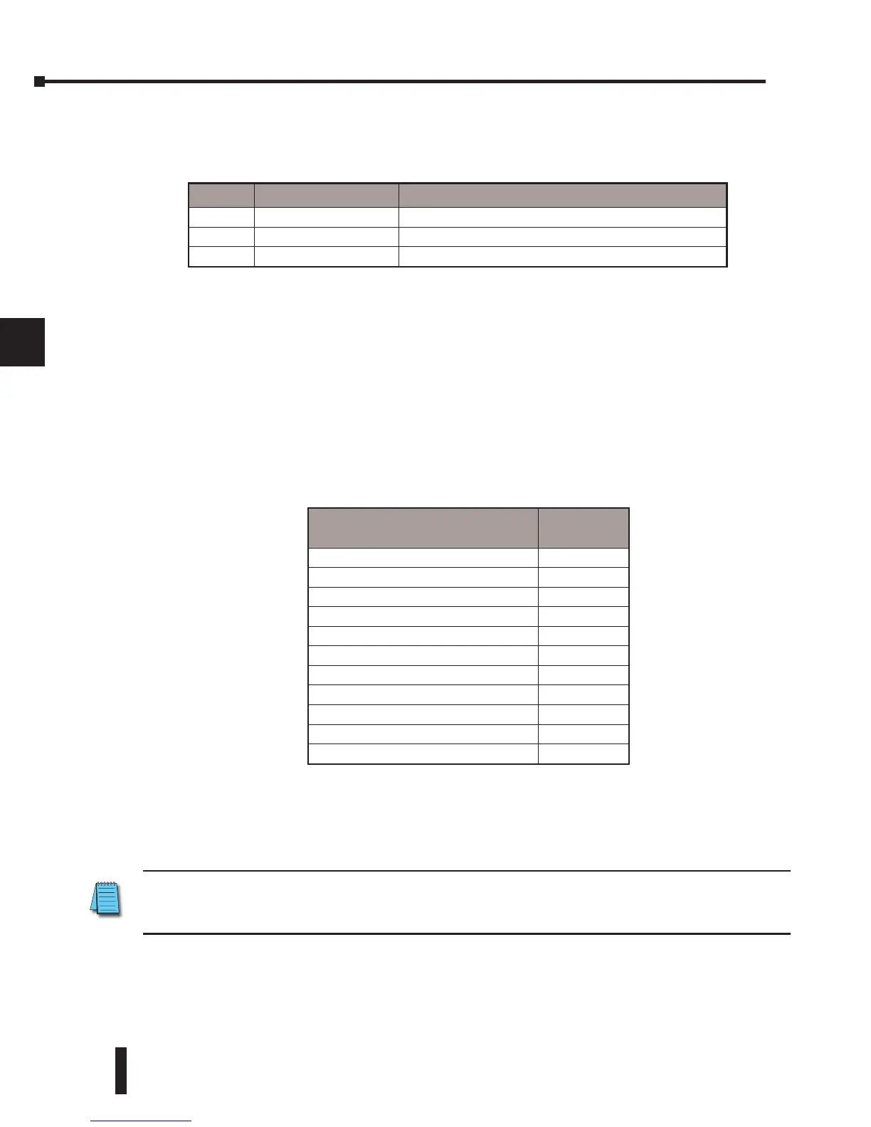
The maximum numbers of characters you can print is 128. The number of characters for each
element is listed in the table below:
The Handheld Programmer’s mnemonic is “PRINT,” followed by the DEF field.
Special relay flags SP116 and SP117 indicate the status of the DL250–1/260 CPU ports (busy,
or communications error). See the appendix on special relays for a description.
NOTE: You must use the appropriate special relay in conjunction with the PRINT command to ensure
the ladder program does not try to PRINT to a port that is still busy from a previous PRINT or WX or RX
instruction.
# Data format Description
1 none Print 1 for an ON state, and 0 for an OFF state
2 : BOOL Print “TRUE” for an ON state, and “FALSE” for an OFF state
3 : ONOFF Print “ON” for an ON state, and “OFF” for an OFF state
Element type
Maximum
Characters
Text, 1 character 1
16-bit binary 6
32-bit binary 11
4-digit BCD 4
8-digit BCD 8
Floating point (real number) 13
Floating point (real with exponent) 13
V-memory/text 2
Bit (1/0 format) 1
Bit (TRUE/FALSE format) 5
Bit (ON/OFF format) 3