V4.7 | 06/24/2024 | 11165414
131
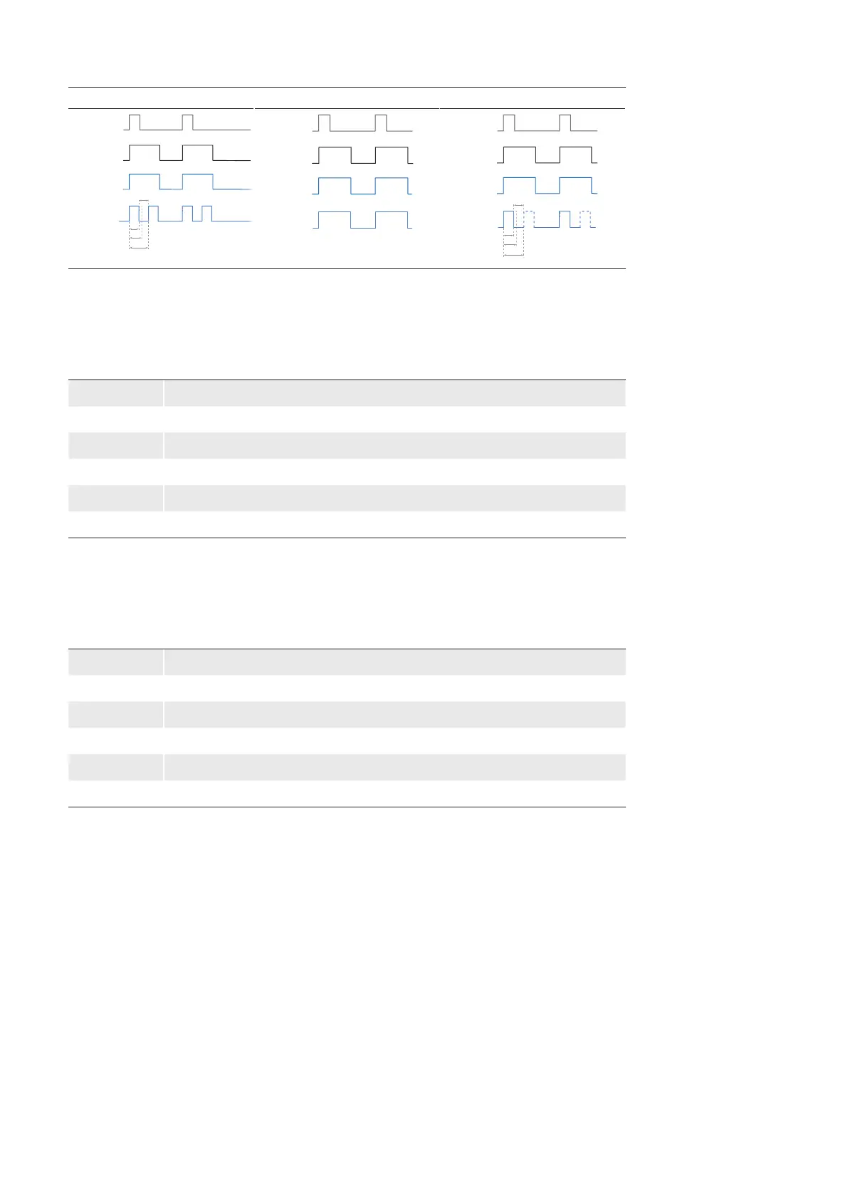
Timing diagrams of the PWMModes:
FixedFrequency O OnePulse
Exposure
LineSource e.g.
ExposureActive
Trigger
LinePWMDuration
LinePWMMaxDuration
LinePWMPeriodTime
LinePWMOffTime
Signal Output
Exposure
LineSource e.g.
ExposureActive
Trigger
Signal Output
Exposure
LineSource e.g.
ExposureActive
Trigger
LinePWMDuration
LinePWMMaxDuration
LinePWMPeriodTime
LinePWMOffTime
Signal Output
7.9.12 LinePWMOTime(only VCXG.I / .XT / .PTP)
Oers the o time included in the PWM Period in microseconds.
Name LinePWMMaxDutyCycle
Category DigitalIOControl
Interface IInteger
Access Read only
Unit µs
Values -9223372036854775808 - 9223372036854775808 (Increment: 1)
7.9.13 LinePWMPeriodTime (only VCXG.I / .XT / .PTP)
Readout of the entire period in μs.
Name LinePWMPeriodTime
Category DigitalIOControl
Interface IInteger
Access Read only
Unit µs
Values depends on PWM settings


 To Next Page