V4.7 | 06/24/2024 | 11165414
134
7.9.15 LineSource
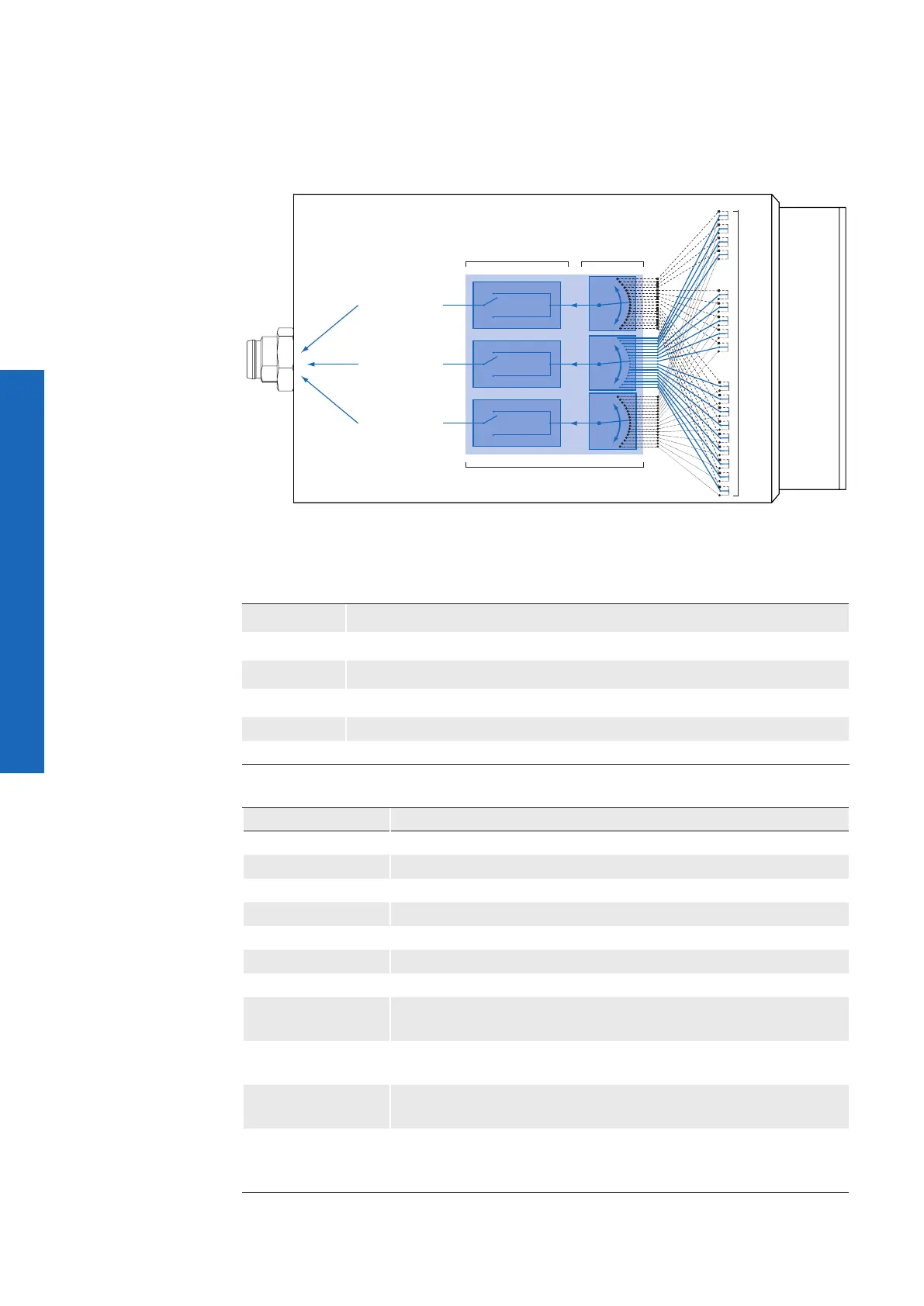
With this feature, Baumer gives you the option to wire the output connectors to internal
signals that are controlled on the software side.
On CX cameras, the output connector can be wired to one of the provided internal signals:
(Output) Line 0
state high
state low
(Output) Line 1*
state high
state low
(Output) Line 2*
state high
state low
IO Matrix
state selection
(inverter)
signal selection
(software side)
Signals
* Example, if the two GPIO's are used as outputs. (only VCXG / VCXU)
* VCXG.I / VCXG.I.XT is equipped with four fixed Outputs (Line0 ... Line3)
Name LineSource
Category DigitalIOControl
Interface IEnumeration
Access Read / Write
Unit -
Values see table below
Signals
ExposureActive Device is doing the exposure of a Frame (or Line).
Off Line output is disabled (Tri-State).
Line 0 Device is currently waiting for signal of input line 0.
Line 1 Device is currently waiting for signal of input line 1.
ReadoutActive Device is doing the readout of a Frame.
Timer1Active The chosen Timer is in active state.
TriggerReady Device is ready for trigger.
UserOutput1
The chosen User Output Bit state as dened by its current Use-
rOutputValue.
UserOutput2
(only ≥ Rel. 2)
The chosen User Output Bit state as dened by its current Use-
rOutputValue.
UserOutput3
(only ≥ Rel. 2)
The chosen User Output Bit state as dened by its current Use-
rOutputValue.
UserOutput4
(only VCXG.I /.XT/
.PTP)
The chosen User Output Bit state as dened by its current Use-
rOutputValue.



 To Next Page