Appendix B: Depot Repair Procedures 173
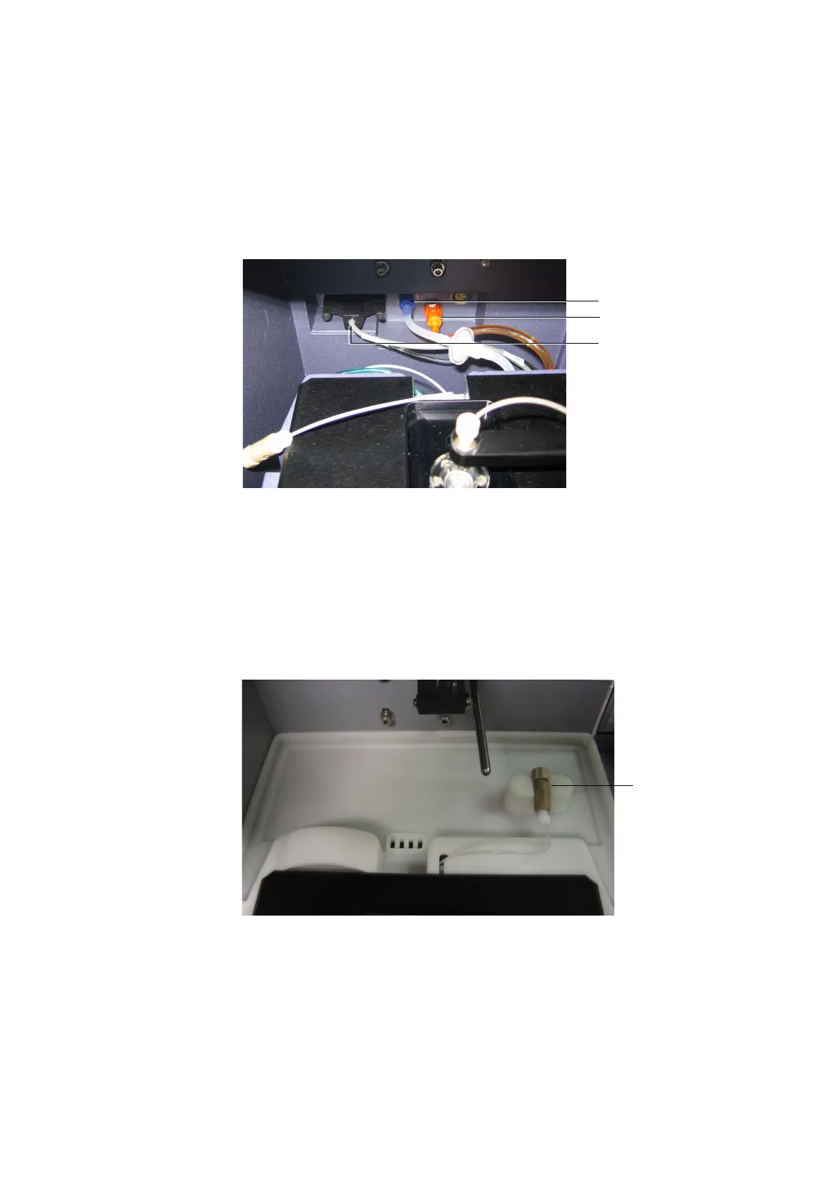
Figure B-10 Connecting BD FACSCanto II interface cable to cytometer
9 [BD FACSCanto] Install the rear catch tray.
- Route the sample coupler underneath the catch tray tongue and sample
coupler slot.
- Push the tray in, making sure the coupler line is not crimped or kinked.
The clamp on the tray is used for the sample coupler when it is not in
use.
Figure B-11 Catch tray installed at the back of the BD FACSCanto
interface/
communication cable
waste line (orange)
sheath line (blue)
clamp for
sample
coupler